

Part of the Kubota Repair Manuals.
This is the factory shop manual for the Kubota L3130, L3430, L3830, L4630, and L5030 tractors, supplied as a 619-page PDF you download and keep. One volume covers all five models and their diesel engines: the D1503, D1703, D1803, V2203, and V2403 in the GST-EU family, built from 2000 to 2007.
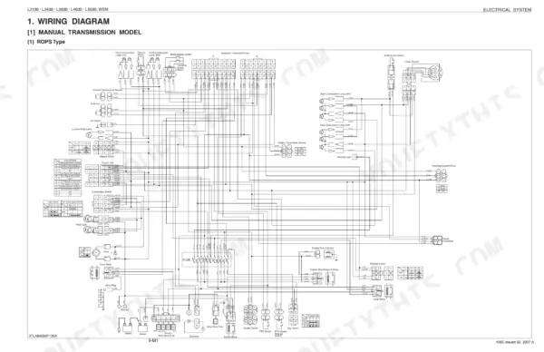
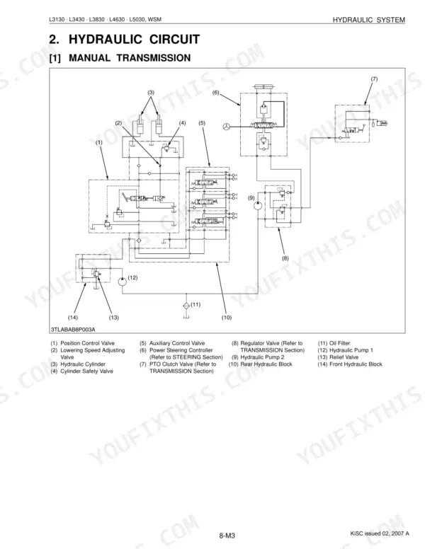
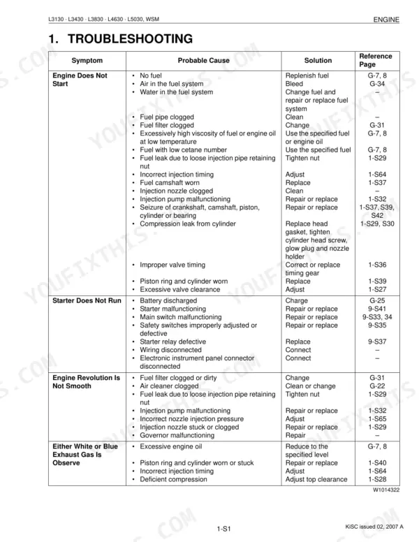
The manual is divided into mechanism and servicing for each system, running from the general section through the engine, clutch, transmission, rear and front axles, brakes, steering, the hydraulic system, the full electrical system, and the cabin with air conditioner.
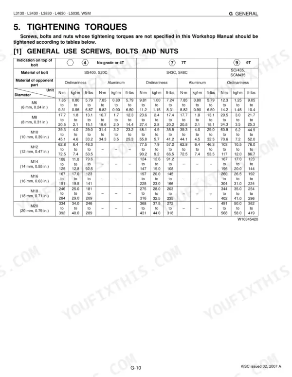
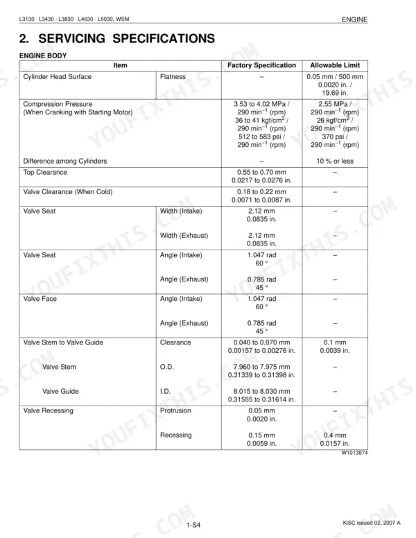
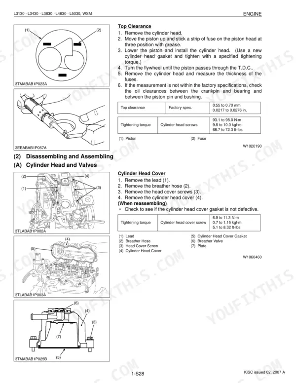
You get construction and function details, factory specifications, allowable limits, torque values, and step-by-step servicing so you can take a repair from diagnosis to reassembly. The file has a text layer and bookmarks, so you can search for a spec or procedure and print only the pages you need at the bench.
What's Inside This Manual
| System | Pages | Key Topics |
|---|---|---|
| G General | 19-80 | Tractor, Electrical Parts, Wiring, Battery, Fuse, Connector, Lubricants, Fuel |
| Engine | 81-152 | Features, Fuel System, Lubricating System, Cooling System |
| Clutch | 153-172 | Clutch Pedal, Clutch Disc, Pressure Plate, Diaphragm Spring, Release Holder, Thrust Ball Bearing |
| Transmission | 173-334 | Main Gear Shift Section, Shuttle Shift Section, Range Gear Shift Section, Front Wheel Drive Section, Creep Gear Shift Section, PTO System |
| Rear Axle | 335-345 | Rear Axle Case, Differential Gear Shaft, Brake Case, Differential Pinion, Final Gear |
| Brakes | 346-361 | Brake Pedal, Brake Lever Link Shaft, Cam Plate, Brake Disc, Parking Brake Lever |
| Front Axle | 362-386 | Axle Flange, Bevel Gear Case, Spiral Bevel Pinion Shaft, Differential Case, Differential Side Gear |
| Steering | 387-413 | Hydraulic Pump, Steering Controller, Control Valve, Metering Device (Gerotor), Relief Valve, Steering Cylinder |
| Hydraulic System | 414-462 | Hydraulic Pump, Front Hydraulic Block, Rear Hydraulic Block, Position Control Valve, Lowering Speed Adjusting Valve, Hydraulic Cylinder |
| Electrical System | 463-555 | Wiring Diagram, Electronic Control Panel, Starting System, Charging System, Lighting System, Color of Wiring |
| Cabin | 556-619 | Air Conditioner System Outline, System Control, Electrical System, A/C Model, Heater Model, Air Conditioner Relay, Blower Relays and Compressor Relay |
Quick Reference Specifications
| Specification | Value | Page |
|---|---|---|
| All Models | ||
| Cylinder head screws | 93.1 to 98.0 N·m (9.5 to 10.0 kgf·m, 68.7 to 72.3 ft-lbs) | p. 98 |
| Rear wheel mounting screws and nuts | 215 N·m (22 kgf·m, 166 ft-lbs) | p. 41 |
| Hydraulic pump assembly mounting screw and nut | 23.5 to 27.5 N·m (2.4 to 2.8 kgf·m, 17.4 to 20.3 ft-lbs) | p. 444 |
| Alternator pulley nut | 58.3 to 78.9 N·m (5.95 to 8.05 kgf·m, 43.0 to 58.2 ft-lbs) | p. 508 |
| Alternator Stator Resistance | Less than 1.0 Ω | p. 507 |
| Bushing to Gear Shaft Clearance Factory spec. | 0.020 to 0.081 mm (0.0008 to 0.0032 in.) | p. 442 |
| Gear Shaft O.D. Factory spec. | 14.970 to 14.980 mm (0.5894 to 0.5898 in.) | p. 442 |
| Side Plate Thickness Allowable limit | 2.40 mm (0.0945 in.) | p. 442 |
| Battery Terminal Connection Potential difference Reference value | Less than 0.1 V | p. 509 |
| L5030 | ||
| Bevel gear case mounting screw | 166.7 to 196.1 N·m (17.0 to 20.0 kgf·m, 123 to 145 ft-lbs) | p. 370 |
| Fuel tank capacity, L5030 | 43 L | p. 28 |
| L3130, L3430, L3830, L4630 | ||
| Fuel tank capacity (L3130, L3430, L3830, L4630) | 40 L | p. 27 |