


This Kubota B7800 Workshop Manual PDF (OEM #9Y011-18201) runs the full tractor lineup, from the compact B-series and L2800 up through the M125X, with factory procedures for every drivetrain variant: hydraulic shuttle shift, swing shift, hydrostatic, and power shift transmissions. It packs 100 pages of hydraulic circuit diagrams that trace fluid through the pump, priority valve, and relief stack, plus wiring schematics for the starting, charging, and lighting systems and 100 pages of exploded views covering clutch types, axle configurations, and the bi-speed turn system. Set HST high-pressure relief at 30.9 to 31.9 MPa and charge relief between 500 and 800 kPa straight from the spec tables. No more chasing numbers through scattered forum threads. Everything is bookmarked by system and keyword-searchable, so you can pull it up on a tablet, walk to the machine, and start wrenching.
What's Inside This Kubota B1410 & variants Manual
| System | Pages | Key Topics |
|---|---|---|
| 1 Engine | 4-5 | Notice |
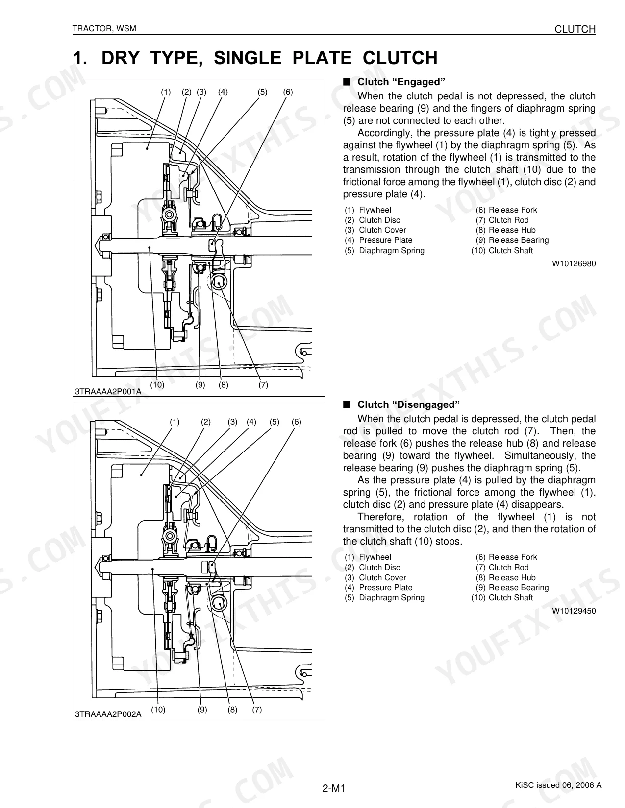
| 2 Clutch | 6-12 | Dry Type, Single Plate Clutch, Dual Stage Clutch, Hydraulic Multiple Disc Clutch (For Travelling), Hydraulic Multiple Disc Clutch (For PTO) |
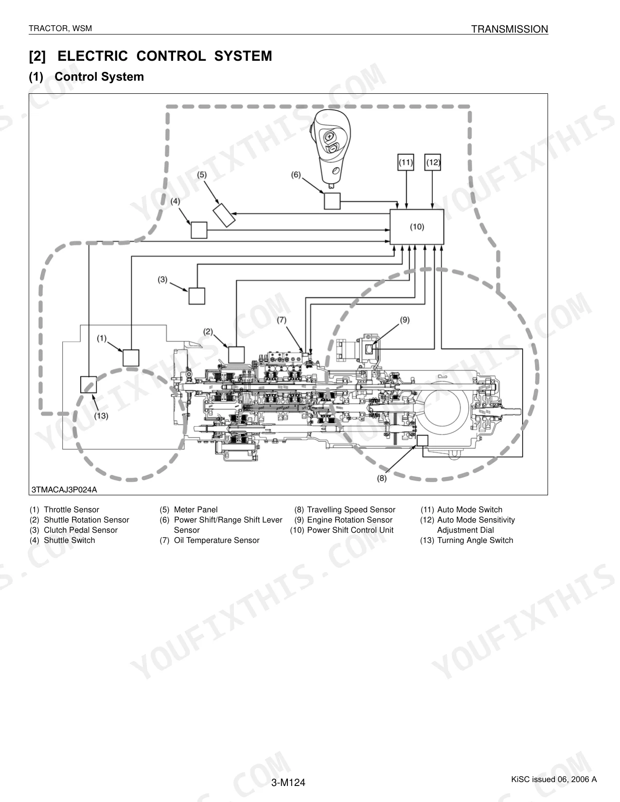
| 3 Transmission | 13-163 | Transmission Gears, Hydraulic Shuttle Shift, Swing Shift, Dual Speed, Hydrostatic Transmission, Power Shift System |
| 4 Rear Axle | 164-167 | Hexagonal Shaft Type, Flange Type, Flange Type with Dropped Axle Case |
| 5 Brakes | 168-184 | Travelling (Foot) Brake (Mechanical Type), Travelling (Foot) Brake (Hydraulic Type), Parking Brake, Hydraulic Trailer Brake (Hydraulic Trailer Brake Valve) |
| 6 Front Axle | 185-197 | Two Wheel Drive, Four Wheel Drive (Standard), Four Wheel Drive (With Bi-Speed Turn System) (Front Axle Type), Four Wheel Drive (With Bi-Speed Turn System) (Transmission Type 1) |
| 7 Steering | 198-229 | Manual Steering (Steering Linkage), Manual Steering (Steering Gear Box), Power Steering (Integral Type), Power Steering (Full Hydrostatic Type), Steering Cylinder |
| 8 Hydraulic System | 230-313 | Hydraulic Circuit Symbols, Hydraulic Pump, Oil Strainer and Filter, Flow Priority Valve, Regulator Valve, Relief Valve |
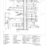
| 9 Electrical System | 314-340 | Starting System, Charging System, Lighting System, Gauges |
| 10 Cabin | 341-367 | Principles of Refrigeration Cycle, Outline of Air Conditioning System, System Layout and Component Part, System Control, Front Windshield Wiper, Rear Windshield Wiper |
| 11 Others | 368-390 | - |
Quick Reference Specifications
| Specification | Value | Page |
|---|---|---|
| All Models | ||
| Refrigerant Type | R134a | p. 345 |
| Refrigerant Charge Amount | 900 to 1000 g (1.98 to 2.21 lbs) | p. 345 |
| HST Type 1 | ||
| Check and High Pressure Relief Valve Operating Pressure (HST Type 1) | 30.9 to 31.9 MPa | p. 53 |
| Charge Relief Valve Operating Pressure (HST Type 1) | 500 to 800 kPa | p. 54 |
| Neutral Valve Operating Pressure (Close, HST Type 1) | 7.36 to 9.81 MPa | p. 55 |
| HST Type 4 | ||
| Charge Relief Valve Setting Pressure (HST Type 4) | 2.25 to 2.45 MPa | p. 89 |
| Case Relief Valve Setting Pressure (HST Type 4) | 0.29 MPa | p. 89 |
| GST Type 1 | ||
| GST Low-pass Valve Closing Setting Pressure | 0.24 MPa | p. 106 |
| Power Shift System | ||
| Regulator Valve Operating Pressure (Power Shift System) | 2.06 to 2.25 MPa | p. 139 |
| Mechanical Type Brakes | ||
| Brake Equalizer Piston Stroke | approx. 4 mm | p. 176 |
| Bi-speed Turn System | ||
| Bi-speed Turn Front Wheel Speed Ratio | 1.53 times higher than standard | p. 190 |
| Full Hydrostatic Type 4 Steering | ||
| Steering Relief Valve Setting Pressure (Full Hydrostatic Type 4) | 11.9 to 12.8 MPa | p. 228 |
Kubota B1410 & variants Common Problems This Manual Covers
Kubota L2800 hydraulic pump whining noise, loader bucket won't lift or raises very slowly p. 230
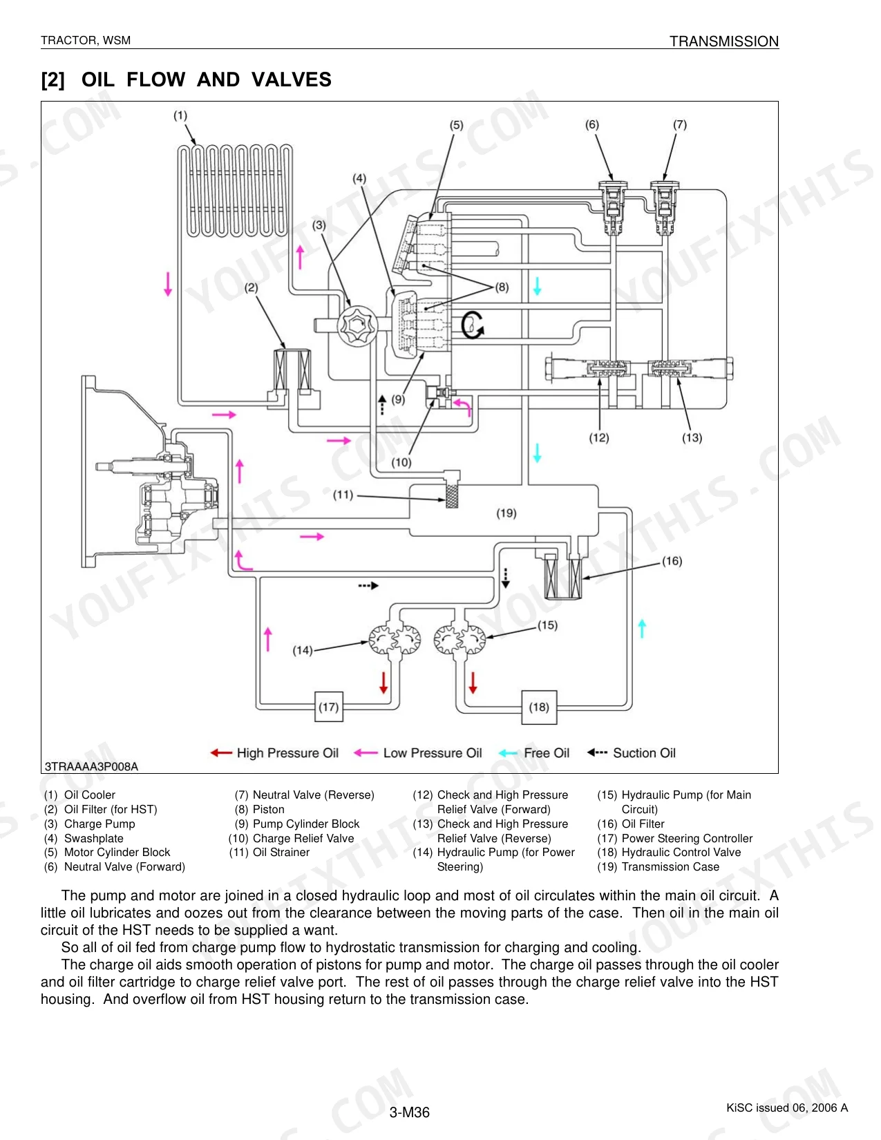
Check hydraulic fluid level, then inspect the oil strainer and filter in the Hydraulic System section (page 230) for debris or contamination. Milky or dark fluid means drain and refill before going further. On HST Type 1 transmissions, test charge relief valve pressure against the 500 to 800 kPa spec (page 54). Replace the valve if pressure falls outside that range.
Manual Section: Hydraulic SystemShifting display blinks continuously and warning buzzer sounds, tractor won't engage gear p. 314
Inspect every solenoid valve connector and the sensor wiring at the transmission for corrosion or loose pins. The fail-safe control throws these symptoms when it reads abnormal electrical signals. On Power Shift System tractors, measure regulator valve operating pressure; the range is 2.06 to 2.25 MPa (page 139). If pressure checks out, trace the wiring diagram starting at page 324.
Manual Section: Electrical SystemBrake pedal feels soft or spongy, tractor pulls to one side under braking p. 168
Drain and refill the brake system with Kubota Super UDT oil if the fluid looks dark or contaminated (brake section starts on page 168). On mechanical-type brakes, measure equalizer piston stroke; spec is approximately 4 mm (page 176). If stroke is off, adjust the brake rod linkage and re-measure before road-testing.
Manual Section: BrakesSteering wheel requires excessive force with engine running, front wheels slow to respond p. 198
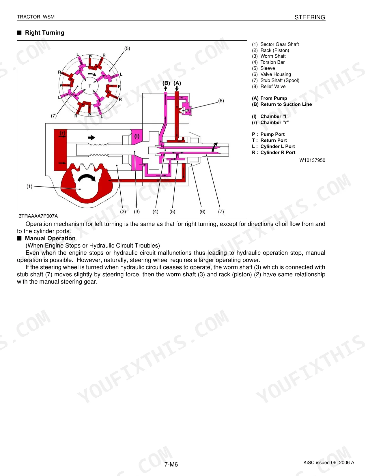
Confirm power steering fluid level and look over the hoses for leaks or kinks before pulling components. If steering stays heavy with the engine running, test the steering relief valve; on Full Hydrostatic Type 4 systems, setting pressure is 11.9 to 12.8 MPa (page 228). For emergency manual operation after a hydraulic failure, the procedure is on page 205.
Manual Section: SteeringCab air conditioning blows warm air, compressor cycles but no cooling p. 341
Verify refrigerant charge with a manifold gauge set; the system takes 900 to 1000 g of R134a (page 345). If the level is correct, check compressor oil: swash plate compressors hold 120 to 135 cc of DENSO ND-OIL 8 PAG oil (page 347). Clear any debris off the condenser fins before recovering and recharging.
Manual Section: CabinFrequently Asked Questions
What fluids and capacities does this machine require?
Fluid types and capacities vary by system. The A/C compressor takes PAG oil, with capacity running 50 to 135 cc depending on type (Swash plate: 120 to 135 cc, Scroll type 2: 60 to 100 cc, Scroll type 3: 50 to 70 cc). Refrigerant is R134a at a charge of 900 to 1000 g (1.98 to 2.21 lbs). Brakes call for Kubota Super UDT oil, and the washer tank holds 2.0 L (2.1 U.S.qts., 1.8 Imp.qts.).
What are the hydraulic system specifications?
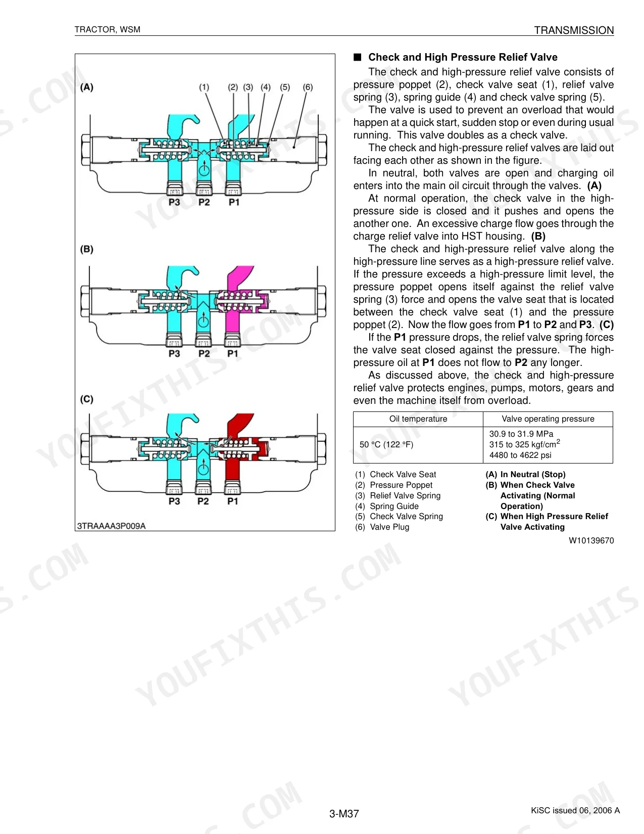
Pressures differ by component and operating condition. The Check and High Pressure Relief Valve runs 30.9 to 31.9 MPa (315 to 325 kgf/cm2, 4480 to 4622 psi) at 50 °C (122 °F). The Charge Relief Valve operates at 500 to 800 kPa (5.1 to 8.2 kgf/cm2, 73 to 116 psi) at the same temperature. The Neutral Valve closes at 7.36 to 9.81 MPa (75 to 100 kgf/cm2, 1067 to 1422 psi) and opens at 1.47 to 2.45 MPa (15 to 25 kgf/cm2, 213 to 356 psi). For the power shift system, the Regulator Valve holds 2.06 to 2.25 MPa (21.0 to 23.0 kgf/cm2, 298.7 to 327.1 psi).
What are the common electrical problems?
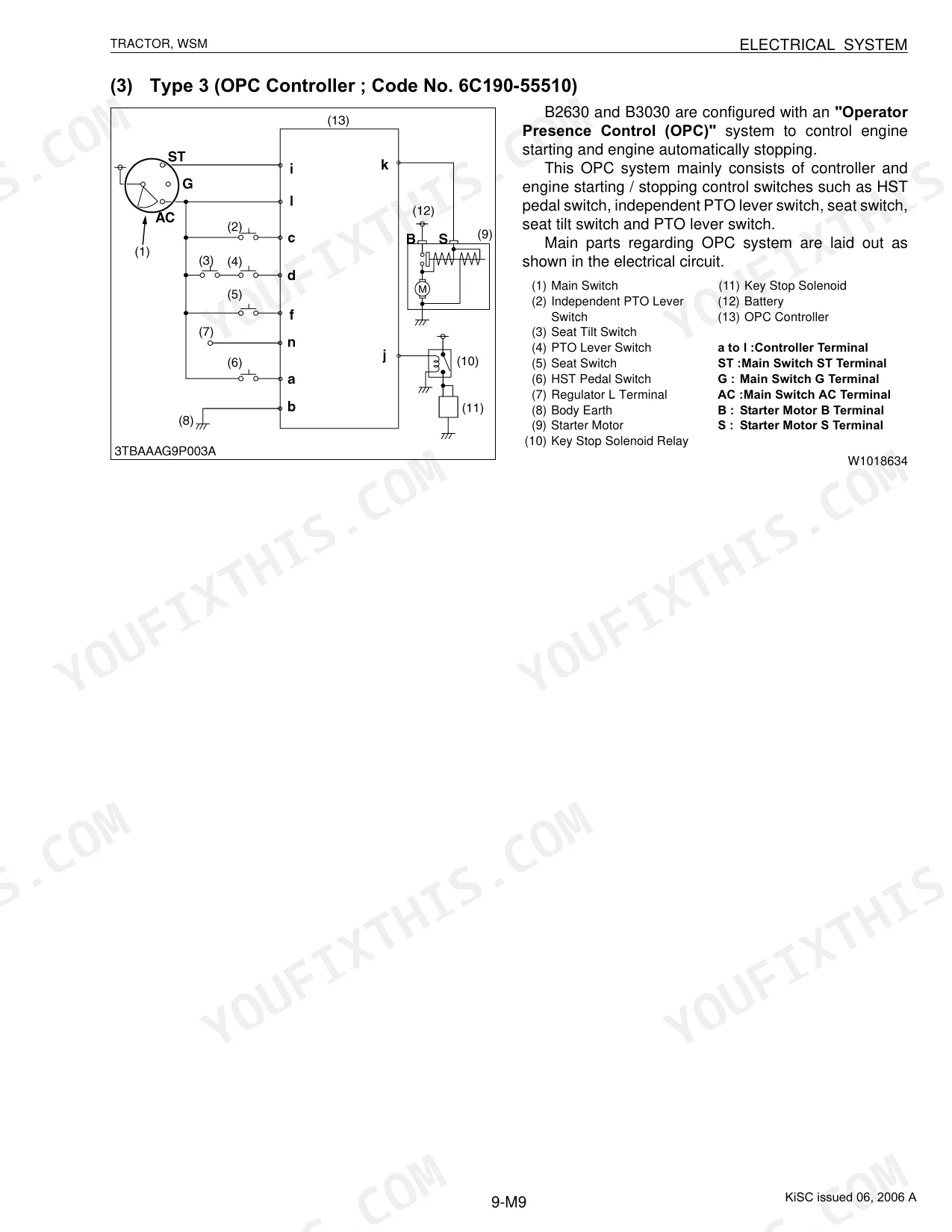
Several conditions trip the warning system: disconnected or short-circuited wiring, faulty sensors or solenoid valves, and low GST valve pressure (below 0.34 MPa, 3.5 kgf/cm2, 50 psi). Warning lights also flag low engine oil pressure, low transmission oil pressure, clogged hydraulic filters, a clogged air cleaner, low fuel, and low brake oil. The system blocks starting unless the safety switches are engaged, and a buzzer sounds if the PTO clutch lever stays on while the operator leaves the seat.
What do I get after purchasing this Kubota B1410 & variants manual?
Immediate download of the complete 390-page searchable Workshop Manual. Open it on any device, whether that's a laptop at your desk or a phone out in the field.
Can I print specific sections of this Kubota B1410 & variants Workshop Manual?
Yes. The PDF carries no DRM, so you can print any page or section you need for the shop. It works with any standard printer.
Can I find hydraulic circuit diagrams in this Kubota B1410 & variants manual?
Yes. The manual includes full hydraulic system diagrams, mapping circuits, valve locations, and component specs across the Kubota B7800 and its B, L, and M series variants.
Document Quality
This document is a scanned PDF with an accurate OCR layer, allowing you to search and copy the full text. The text is crisp and consistently easy to read across all pages. Diagrams and illustrations are clear raster images, with all labels and details perfectly legible. The pages are clean, free from scan artifacts, stains, or skewed content. You will find several blank pages that function as chapter dividers.


Reviews
There are no reviews yet.