


Part of the Kubota Repair Manuals.
Kubota built the STV32, STV36, and STV40 around shared systems, and this 383-page OEM workshop manual (#9Y011-13041) walks through each one: engine, clutch, transmission, rear axle, brakes, front axle, steering, hydraulic, and electrical. Wiring diagrams cover the starting, charging, and lighting circuits; the hydraulic schematics map the full HST loop, power steering circuit, three-point lift, and auxiliary control valve. Test value tables hand you real pass/fail numbers instead of guesswork. Capacities are laid out in plain tables too: 6.7 L in the crankcase, 29.5 L in the fuel tank, and an engine oil change every 100 hours. When the tractor is down, every idle hour costs you. Open the bookmarked PDF on a tablet, tap straight to the section you need, and get back to work.
What's Inside This Kubota STV32, STV36, STV40 Manual
| System | Pages | Key Topics |
|---|---|---|
| G General | 13-66 | General |
| Engine | 67-135 | Lubricating System, Cooling System, Fuel System, Cylinder Head and Valves, Timing Gears, Crankshaft |
| Clutch | 136-146 | Linkage Mechanism, Clutch Disc, Pressure Plate, Release Fork, Release Bearing, Clutch Pedal |
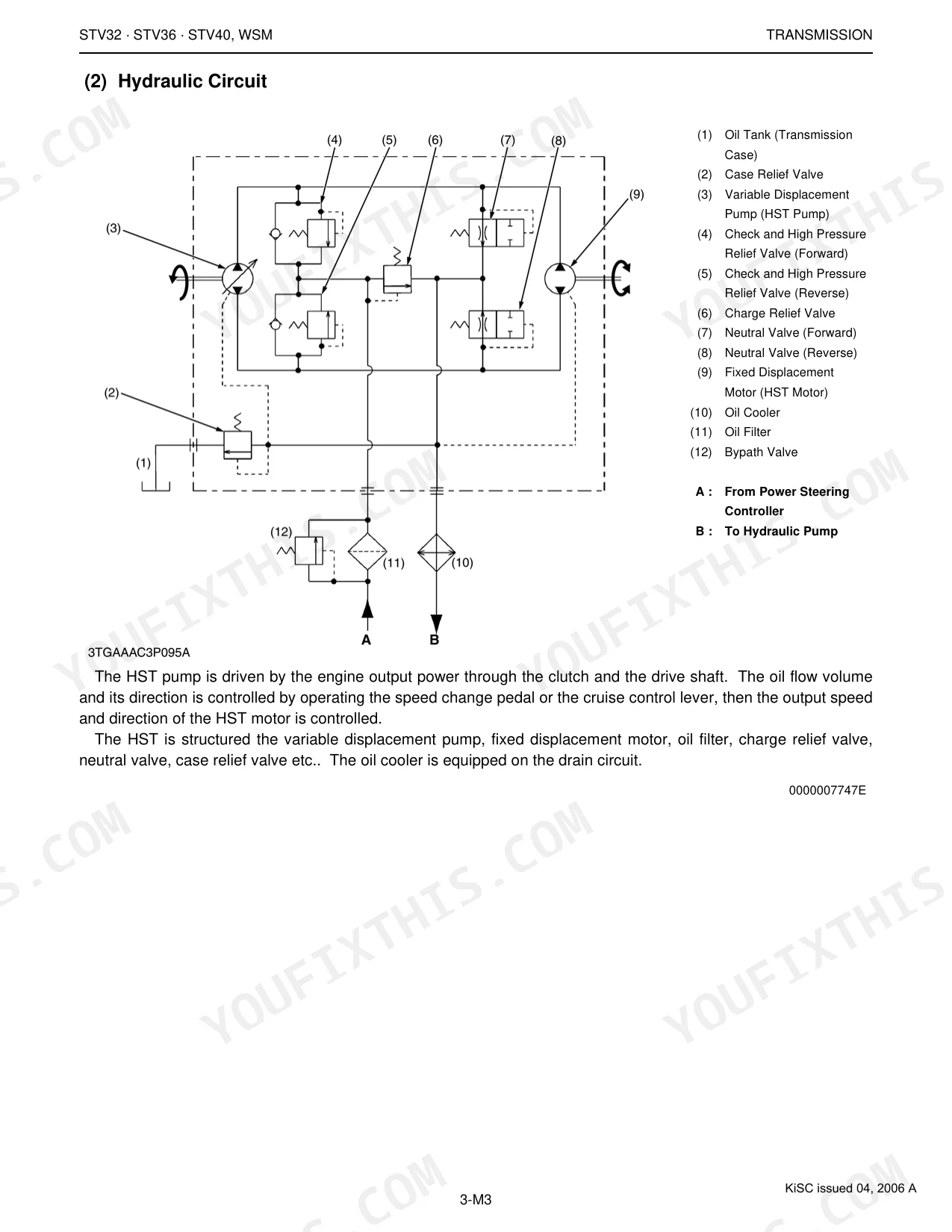
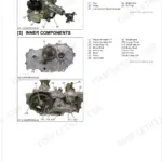
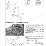
| Transmission | 147-230 | Hydrostatic Transmission (HST), Range Gear Shift Section, Front Wheel Drive Section, Bi-Speed Turn System, Independent PTO System, Rear PTO Gear Shift Section |
| Rear Axle | 231-241 | Structure, Final Reduction System, Planetary Gear, Differential Lock Clutch, Rear Axle Shaft, Hypoid Ring Gear |
| Brakes | 242-252 | Brake Linkage, Parking Brake, Brake Disc, Brake Cam, Brake Plate, Brake Pedal |
| Front Axle | 253-270 | Structure, Front Axle Case, Differential System, Bevel Gear, Differential Pinion, Front Axle Bracket |
| Steering | 271-282 | Structure, Hydraulic Circuit for Power Steering, Steering Cylinder, Steering Controller, Hydraulic Pump, Regulating Valve |
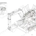
| Hydraulic System | 283-329 | Whole Hydraulic Circuit, Hydraulic Pump, Regulator Valve, Bi-Speed Valve, Three Point Hydraulic System, Auxiliary Control Valve |
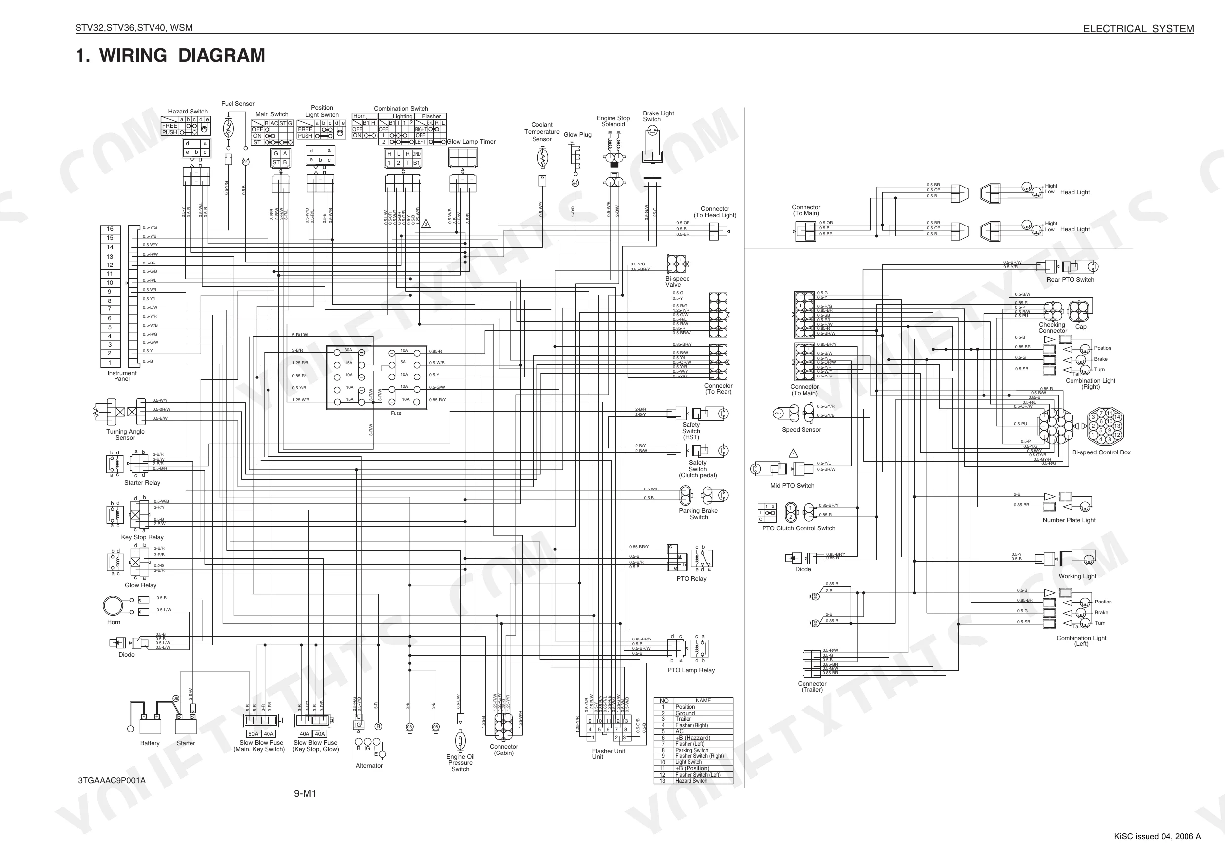
| Electrical System | 330-383 | Wiring Diagram, Starting System, Charging System, Lighting System, Bi-Speed Turn System, Others |
Quick Reference Specifications
| Specification | Value | Page |
|---|---|---|
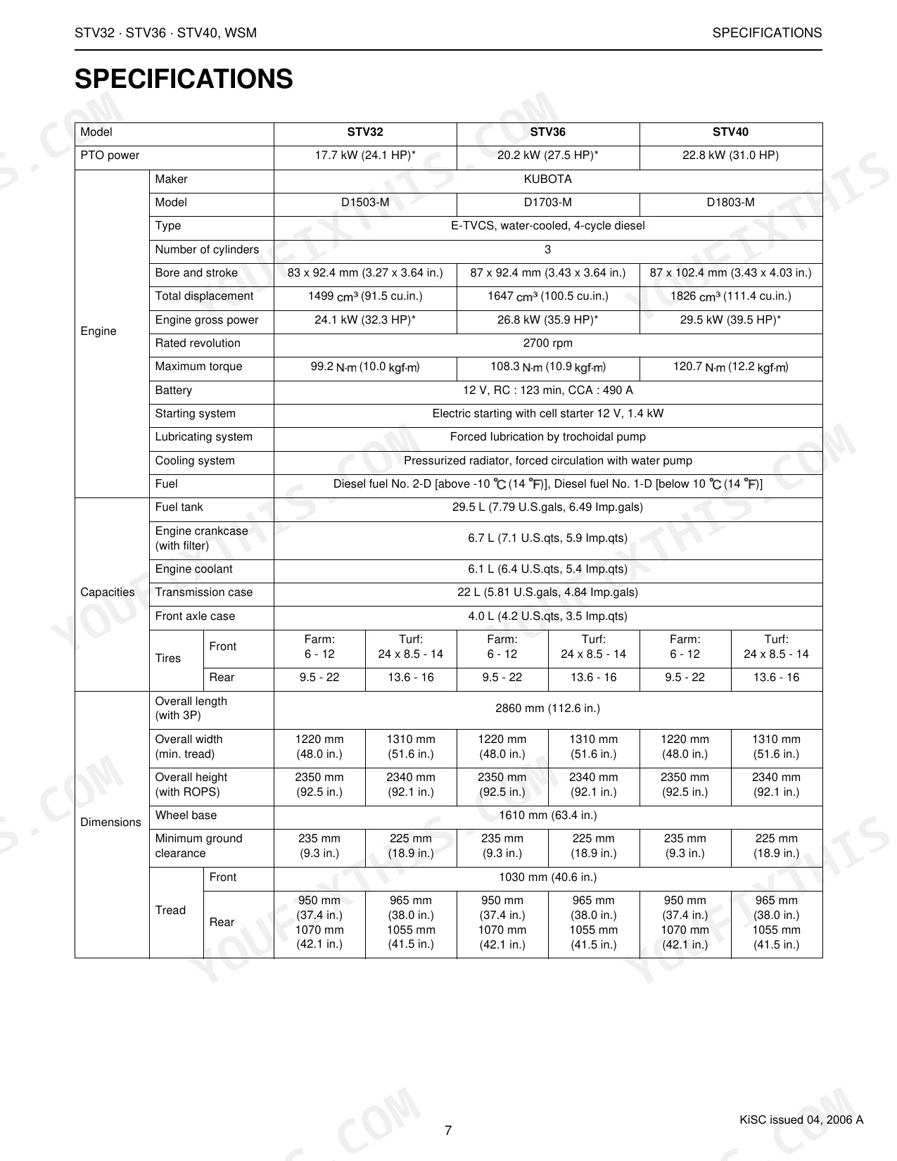
| Fuel tank capacity | 29.5 L (7.79 U.S.gals, 6.49 Imp.gals) | p. 22 |
| Coolant capacity (with reserve tank) | 6.1 L (6.4 U.S.qts, 5.4 Imp.qts) | p. 22 |
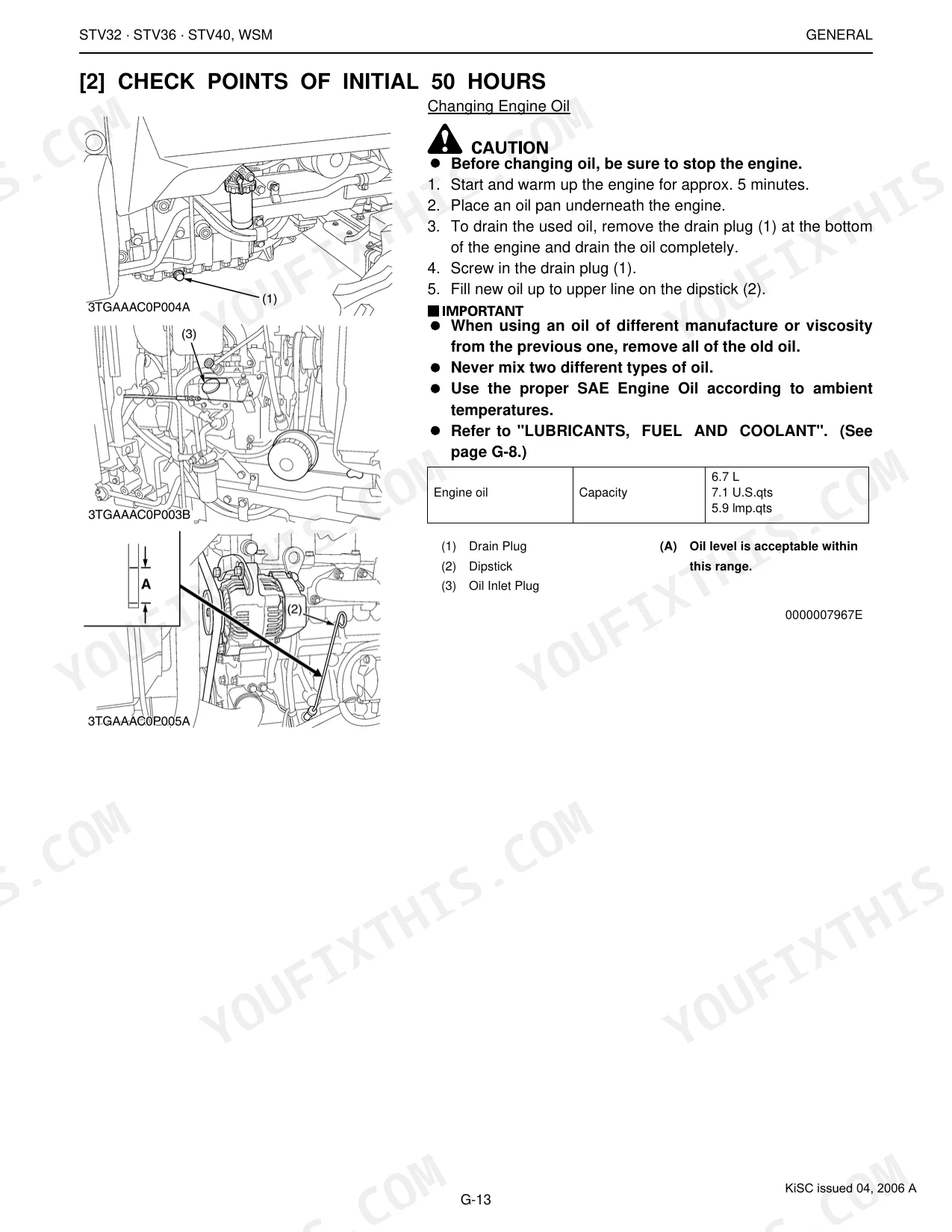
| Engine oil change interval | Every 100 hours | p. 24 |
| Engine oil filter replacement interval | Every 200 hours | p. 24 |
| General use screws, bolts and nuts (M6, No-grade or 4T, Ordinariness) | 7.85 to 9.31 N·m (0.80 to 0.95 kgf·m, 5.79 to 6.87 ft-lbs) | p. 23 |
| General use screws, bolts and nuts (M8, No-grade or 4T, Ordinariness) | 17.7 to 20.5 N·m (1.8 to 2.1 kgf·m, 13.1 to 15.1 ft-lbs) | p. 23 |
| Engine Oil Capacity (with filter) | 6.7 L (7.1 U.S.qts, 5.9 Imp.qts) | p. 9 |
| Transmission Case Capacity | 22 L (5.81 U.S.qts, 4.84 Imp.gals) | p. 9 |
| Front Axle Case Capacity | 4.0 L (4.2 U.S.qts, 3.5 Imp.qts) | p. 9 |
| Cylinder Head Surface Flatness (Allowable Limit) | 0.05 mm / 500 mm (0.0020 in. / 19.69 in.) | p. 76 |
| Valve Clearance (When Cold) | 0.18 to 0.22 mm (0.0071 to 0.0087 in.) | p. 76 |
| Fan Belt Tension (Deflection) | 7.0 to 9.0 mm (0.28 to 0.35 in.) | p. 80 |
Kubota STV32, STV36, STV40 Common Problems This Manual Covers
Kubota STV36 engine cranks slowly and won't start in cold morning temperatures
Inspect the battery terminals for corrosion and test charge voltage before cranking. Confirm the fuel shutoff is fully open and check the air cleaner; clean it every 100 hours per the maintenance schedule on page 24. If it still won't fire, measure valve clearance on page 76: spec is 0.18 to 0.22 mm cold.
Manual Section: Engine Starting & Running IssuesHydrostatic transmission sluggish, tractor loses drive power under load in the field
Top off the transmission fluid first; total case capacity is 22 L (5.81 U.S.gals), with a change due every 400 hours per the maintenance schedule on page 25. Trace charge circuit flow on the HST hydraulic schematic, then check the control linkage from the HST pedal to the servo valve for wear or play.
Manual Section: Hydrostatic Transmission (HST) Operation IssuesClutch pedal goes to the floor, gear changes grind or won't engage
Measure clutch pedal free travel: spec is 20 to 30 mm (0.78 to 1.18 in.) per page 141. Turn the pushrod at the release fork until travel falls within spec. If the pedal still drags, pull the clutch disc and inspect the friction surface and pressure plate for wear.
Manual Section: Clutch System Malfunctions p. 141Three-point hitch won't lift the implement fully or drops back slowly under load
Start at the transmission case fluid level; total capacity is 22 L (5.81 U.S.gals), changed every 400 hours. Check the regulator valve and lift control rod for binding or damage, then work through the Hydraulic System section from page 283 to isolate whether the pump, regulator valve, or control valve is at fault.
Manual Section: Hydraulic System (3-Point Linkage) Performance p. 283Tractor pulls to one side when braking, or pedal travel is excessive
Compare both brake pedals for equal adjustment; uneven linkage is the usual culprit. Check front tire pressure on both sides: spec is 180 kPa (1.8 kgf/cm², 25.6 psi) per page 61. Pull the brake discs and cams from the Brakes section and look for glazing, oil contamination, or uneven friction surface wear.
Manual Section: Braking System Problems p. 242Battery drains overnight, starter motor won't engage, or dashboard instruments are dark
Load-test the battery and check the main fuse. Inspect fan belt deflection on page 80: spec is 7.0 to 9.0 mm (0.28 to 0.35 in.), since a slipping belt keeps the alternator from charging. Trace the fault through the wiring diagram; the Electrical System section breaks starting, charging, and lighting faults down by circuit.
Manual Section: Electrical System General Faults p. 330Frequently Asked Questions
What are the recommended service intervals?
The maintenance check list spells out each interval: greasing every 50 hours, an engine oil change every 100 hours, and the engine oil filter replaced every 200 hours. The fuel filter element gets cleaned every 100 hours and replaced every 400 hours. For the full schedule, see pages G-10 and G-11. p. 24
What fluids and capacities does this machine require?
This machine takes No. 2-D diesel fuel (or No. 1-D below -10 °C) in its 29.5 L (7.79 U.S.gals) tank. The engine crankcase with filter holds 6.7 L (7.1 U.S.qts) of API service CC or CD class oil. The transmission case needs 22 L (5.81 U.S.qts) of KUBOTA SUPER UDT fluid, and the front differential case takes 4.0 L (4.2 U.S.qts) of KUBOTA SUPER UDT fluid or SAE80, 90 gear oil. Coolant capacity is 6.1 L (6.4 U.S.qts) of fresh clean water with anti-freeze. p. 22
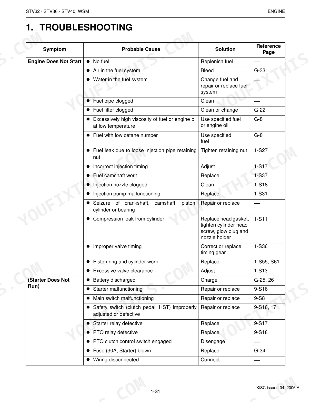
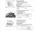
How to troubleshoot engine won't start?
When the engine won't start, the usual causes are no fuel, air in the fuel system, or a clogged fuel filter (see pages G-33 and G-22). Other culprits: incorrect injection timing (adjust per page 1-S17), a worn fuel camshaft (replace per page 1-S37), or a discharged battery (charge per page G-25, 26). If the starter itself won't run, check the safety switches (page 9-S16, 17) or a blown 30A starter fuse (page G-34). p. 73
What are the hydraulic system specifications?
Power steering hydraulic pump delivery runs 14.0 L/min (3.70 U.S.gals./min) at no pressure and 13.72 L/min (3.62 U.S.gals./min) at rated pressure, with an allowable limit of 12.25 L/min. The 3P hydraulic system pump delivers 23.04 L/min (6.09 U.S.gals./min) at no pressure. Relief valve setting pressure for the 3P system is 16.7 to 17.2 MPa (170 to 175 kgf/cm²). p. 304
What do I get after purchasing this Kubota STV32, STV36, STV40 manual?
A 383-page Workshop Manual in searchable PDF, ready to download the moment checkout completes. Open it on a computer, tablet, or phone with no shipping wait.
Are there any print restrictions on this Kubota STV32, STV36, STV40 manual?
No restrictions at all. Print individual pages, full chapters, or the entire manual. The PDF is completely unlocked.
Are there wiring harness diagrams in this Kubota STV32, STV36, STV40 manual?
Complete wiring diagrams are included, covering all electrical circuits, harness routing, and connector pinouts for the Kubota STV32, STV36, STV40.


Reviews
There are no reviews yet.