


Part of the Case Repair Manuals.
This service manual covers the Case 40 XT, 60 XT, and 70 XT compact skid steers, produced by the Case training centre and running 214 pages. All three models share the Case 4-390 four-cylinder diesel, with a turbocharged version on the 70 XT.The manual is organized by system: presentation and specifications, location of the main components, individual component service, the electrical system, the hydraulic system, and the hydrostatic drive system. It carries full electrical circuit diagrams and troubleshooting alongside hydraulic and hydrostatic schematics.You get capacities and lubrication data, component identification and removal, relief and control valve pressures, and the hydrostatic start-up procedure, so you can trace a drive, hydraulic, or electrical fault back to the right part and set it correctly.
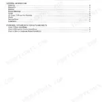
What's Inside This Case 40 XT, 60 XT, 70 XT Manual
| System | Pages | Key Topics |
|---|---|---|
| Introduction | 3-6 | Skid Steer Range (Xt 40, Xt 60, Xt 70), Manual Section Overview, Model Identification |
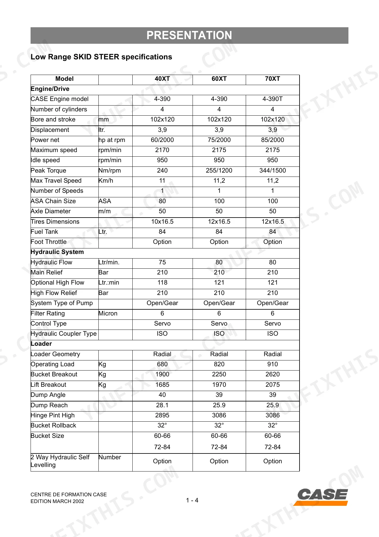
| Presentation | 7-16 | Low Range Specifications, Capacities and Lubrication, Engine Lubrication, Diesel Fuel System, Case Engine, Drive Selection, Control Panels Left and Right Hand Side |
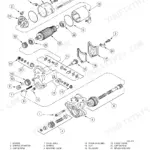
| Location of the Main Components | 17-28 | Hydraulic Pump, Hydrostatic Drive Pump, Hydraulic Drive Motor, Hydraulic Brakes, Loader Valve, Auxiliary Valve, Solenoid Valve, Hydraulic Cylinders |
| Components | 29-56 | Hand Remote Control, Foot Remote Control, Hydrostatic Pump, Hydrostatic Drive Motor, Hydraulic Pump, Loader Valve, Main Relief Valve, Auxiliary Valve |
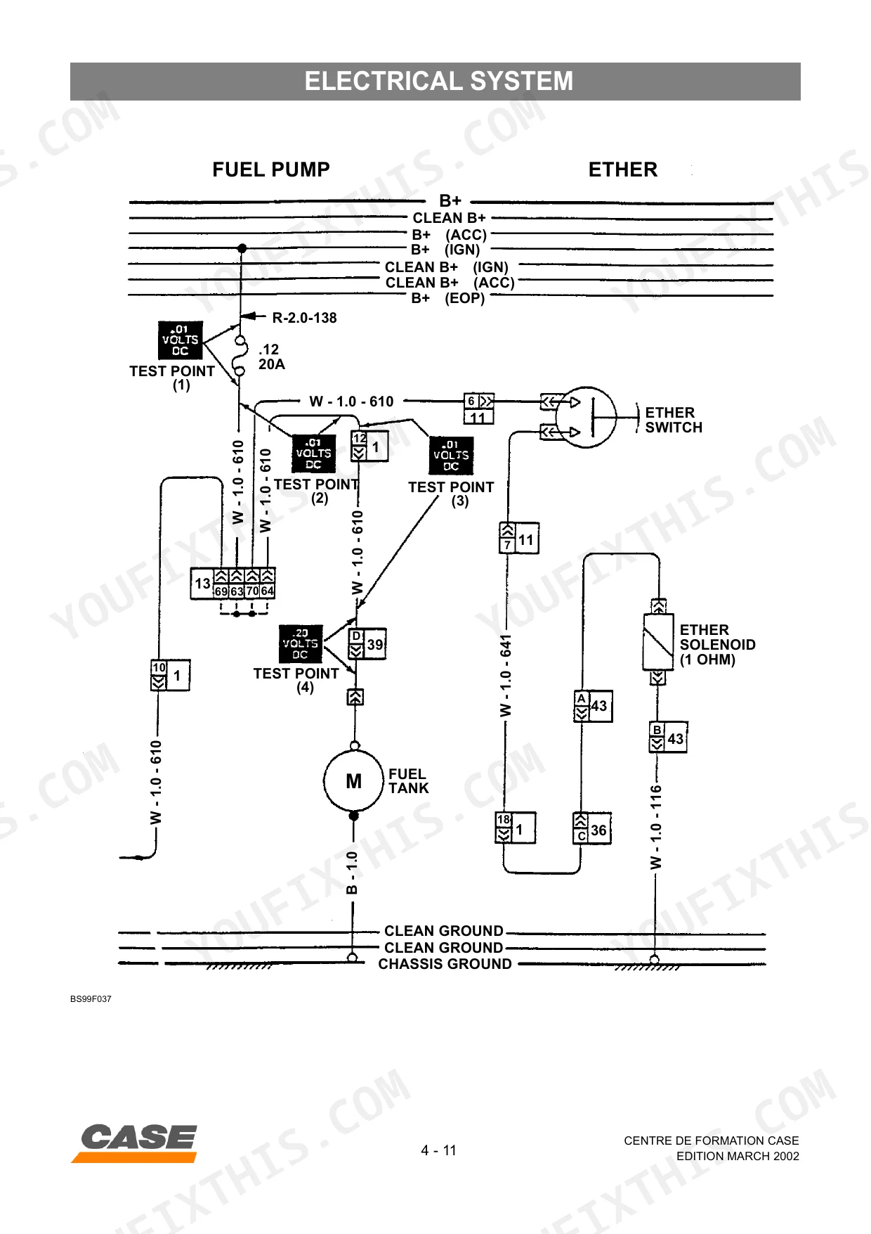
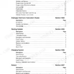
| Electrical System | 57-114 | Circuit Diagram Legends, Fuses (Left Hand Side Instrument Panel, Standard Right Hand Instrument Panel, Optional Engine Shutdown System) |
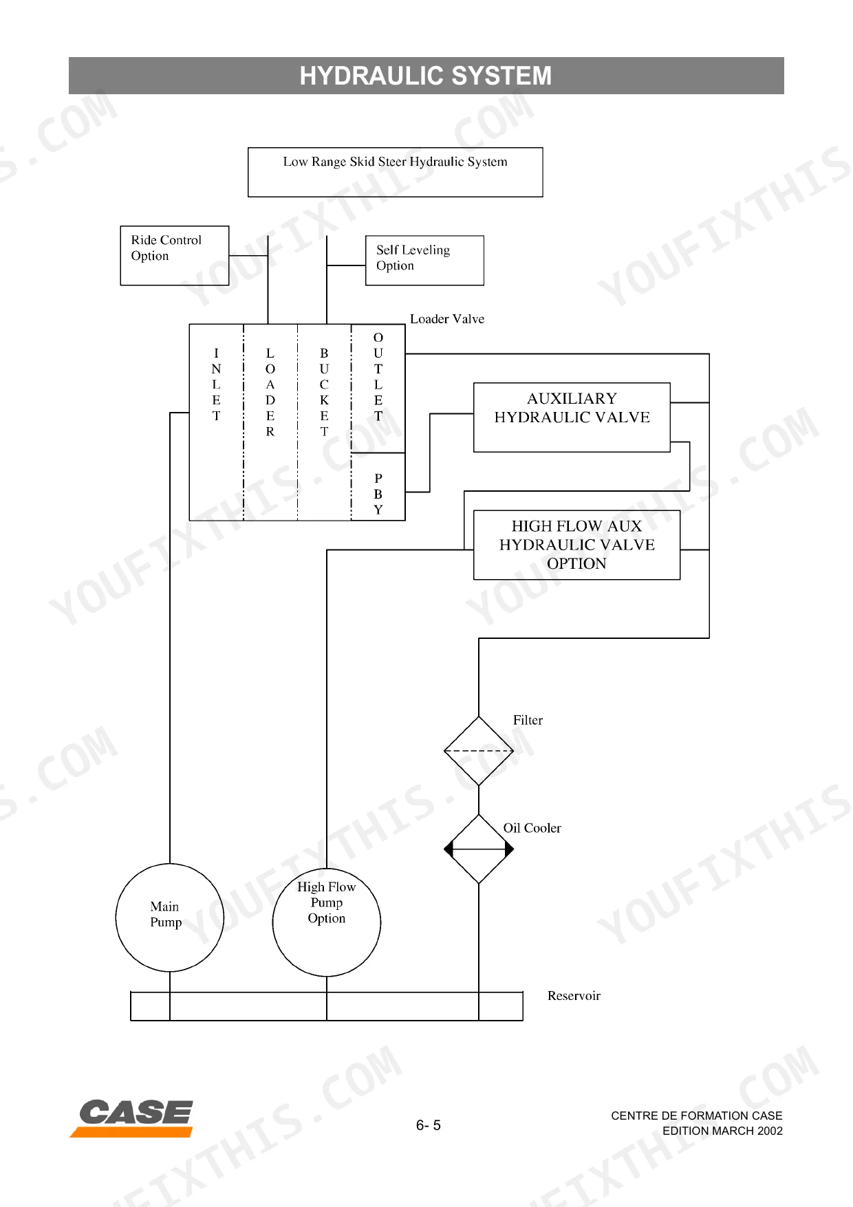
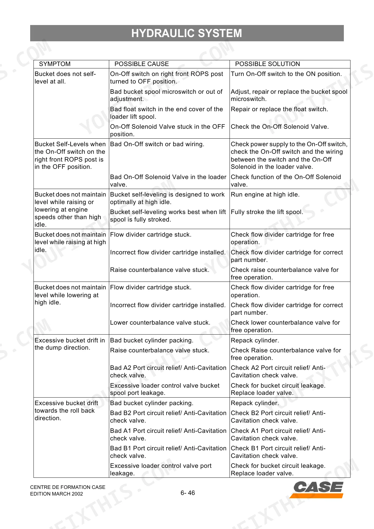
| Hydraulic System | 115-170 | Hydraulic System Overview, Hydraulic Components, Loader Control Valve, Relief and Anti Cavitation Valve, Loader Control Valve Activated in the Different Functions |
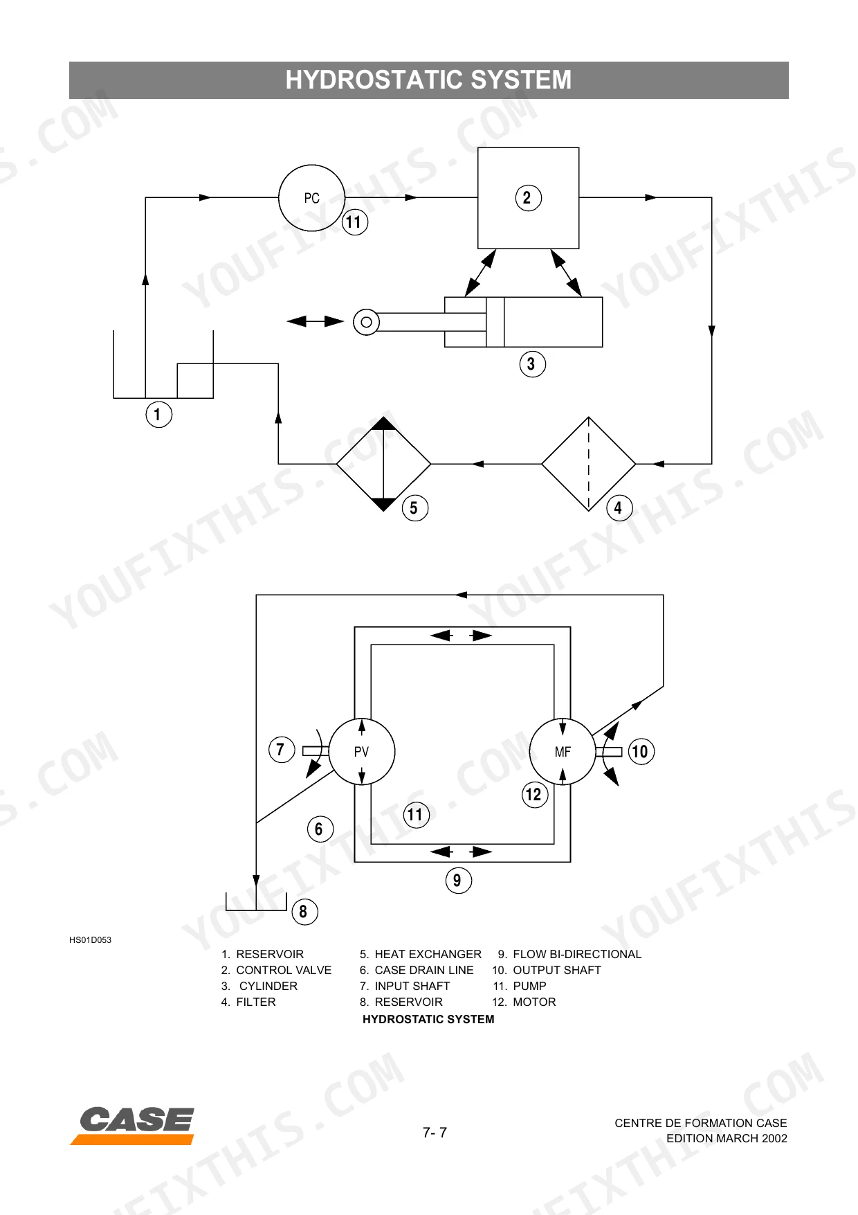
| Hydrostatic System | 171-214 | System Overview, Hydrostatic Pump, Hydraulic Drive Motor, Mechanical Parking Brake, Hydraulic Parking Brake, Hydrostatic Control Linkage, Cleaning Advice, Troubleshooting |
Quick Reference Specifications
| Specification | Value | Page |
|---|---|---|
| All Models | ||
| Hydrostatic System Reset / Start-Up | See Hydrostatic Start-Up Procedure (p. 197) | p. 197 |
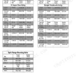
| Hydraulic System Filter Rating | 6 Micron | p. 10 |
| Differential pressure for filter light activation | 40 psi | p. 118 |
| Hydraulic System Main Relief Bar | 210 Bar | p. 10 |
| Hydraulic System High Flow Relief Bar | 210 Bar | p. 10 |
| Hydrostatic Drive Motor Manufacturer | EATON | p. 21 |
| Hydrostatic Drive Motor Type | Geroler | p. 21 |
| Engine Displacement | 3.9 ltr. | p. 10 |
| Fuel Tank Capacity | 84 Ltr. | p. 10 |
| 40XT | ||
| Hydraulic Flow | 75 Ltr/min | p. 10 |
| 60XT, 70XT | ||
| Hydraulic Flow | 80 Ltr/min | p. 10 |
Case 40 XT, 60 XT, 70 XT Common Problems This Manual Covers
Weak hydrostatic drive
The machine creeps slowly or loses tractive power when charge pressure is low, the relief is misadjusted, or the pump is worn. This section covers the hydrostatic system with its pressures and start-up procedure.
Manual Section: Hydrostatic System p. 171Sluggish bucket or auxiliary hydraulics
Loader and auxiliary functions turn slow or fail to reach pressure when the main relief drifts out of spec or the pump wears. This section covers the hydraulic system and its relief valve pressures.
Manual Section: Hydraulic System p. 115Hard starting or stalling
Water in the fuel and clogged filters are a common cause of no-start and power loss on these engines. This section covers the diesel fuel system and its service.
Manual Section: Presentation p. 7One-side drive imbalance
A machine that pulls to one side or loses drive on one track points to hydrostatic pump or motor wear or a linkage issue. This section covers the hydrostatic pump and drive motor components.
Manual Section: Components p. 29Warning lights or electrical faults
Intermittent warning lights and dead circuits trace to fuses, wiring, or the instrument panels. The electrical section provides circuit diagram legends, fuse layouts, and wiring harness tests.
Manual Section: Electrical System p. 57Hydraulic overheating and pressure loss
Overheating, noise, or falling performance after warm-up follows low oil, a clogged filter or cooler, or incorrect relief settings. This section locates the pump, relief, and cooler for checking.
Manual Section: Location of the Main Components p. 17Frequently Asked Questions
Which skid steers does this manual cover?
It covers the Case 40 XT, 60 XT, and 70 XT compact skid steers, all built on the Case 4-390 diesel engine.
What are the engine and capacity specs?
The presentation section lists the 3.9 litre Case 4-390 diesel, an 84 litre fuel tank, a 16.6 litre cooling system, and a 10.4 litre engine oil capacity with filter change. p. 7
What is the hydraulic relief pressure?
The hydraulic system runs a 210 bar main relief, with standard flow of 75 litres per minute on the 40 XT and 80 litres per minute on the 60 XT and 70 XT. p. 115
Does it include wiring diagrams and troubleshooting?
Yes. The electrical section carries the full circuit diagrams, fuse layouts, control lever wiring, and harness testing and troubleshooting for the XT skid steers. p. 57
What do I get after purchasing this Case 40 XT, 60 XT, 70 XT manual?
Checkout delivers a 214-page searchable PDF instantly. Open it on a laptop, tablet, or phone and take it straight to the shop floor.
Is this Case 40 XT, 60 XT, 70 XT Service Manual printable?
Yes. The PDF carries no DRM, so you can print any page or section you need for your shop on a standard printer.
Are electrical wiring diagrams included in this Case 40 XT, 60 XT, 70 XT manual?
Yes, this Case 40 XT, 60 XT, 70 XT Service Manual includes complete electrical wiring diagrams, wire routing, and connector pinouts.


Reviews
There are no reviews yet.