

Part of the Case Repair Manuals.
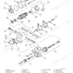
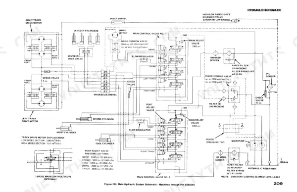
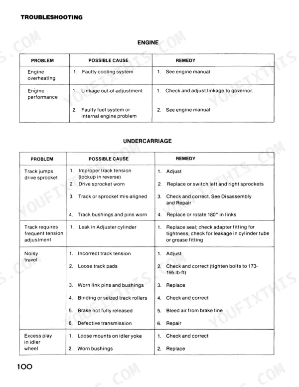
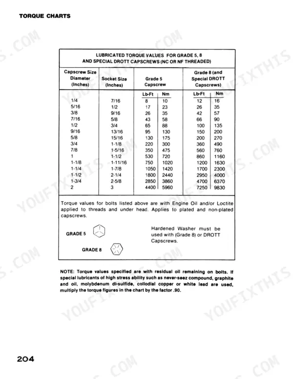
Looking for a Case 50 service manual PDF that actually came from the factory? This 217-page manual (OEM #S 406236M2) covers the Case 50 crawler excavator from undercarriage to boom tip. Inside: hydraulic schematics with full circuit routing for the summated pump system, wiring diagrams for both the 12/24-volt and later 24-volt machines, and a troubleshooting section that walks the swing, track drive, and pilot control circuits fault by fault. You also get page after page of teardown procedures, from the swing gearbox and track drive motor to the turntable bearing swap. Torque the 3/4-inch turntable capscrews to 360 lb-ft (490 Nm) and set the by-pass check valve at 65 psi (450 kPa). No more chasing hydraulic pressure drops with a gauge and a guess. Bookmarked PDF opens on any device; carry it to the machine on your tablet and start wrenching.
What's Inside This Case 50 Manual
| System | Pages | Key Topics |
|---|---|---|
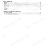
| General | 5-10 | Safety Precautions, Introduction, Nomenclature and General Description, Specifications |
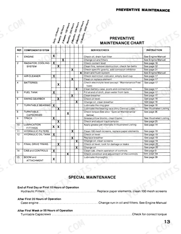
| Scheduled Preventive Maintenance | 11-23 | Introduction, Hydraulic Oil Recommendations, Hydraulic System Operating Pressures, Component Capacities, Rated Pump Output, Maintenance Chart |
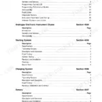
| Mechanical System | 24-44 | Undercarriage, Engine and Related Parts, Turntable Swing, Boom and Attachments |
| Electrical System | 45-64 | Charging and Starting System, Control Circuits, Lights and Instrumentation Circuits, Alternator, Voltage Regulator, Batteries |
| Hydraulic System | 65-99 | Introduction, System Maintenance |
| Troubleshooting | 100-116 | Introduction, Engine, Undercarriage, Electrical System, Pilot Control System, Main Hydraulic System, Track Drive System, Swing System |
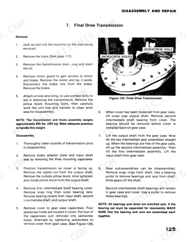
| Undercarriage Component Service | 117-130 | Track Chain, Track Adjustment Cylinder, Track Rollers, Idler Wheel, Digging Brake, Final Drive Transmission |
| Engine Drive, Brakes, Swing Gearbox and Turntable | 131-148 | Engine and Pump Drive, House Brake, Swing Gearbox, Turntable Bearing Replacement |
| Boom, Dipperstick and Wiring Harness | 149-150 | Boom, Wiring Harness Replacement |
| Hydraulic Pumps and Control Valves | 150-171 | Main Hydraulic Pump, Pilot Hydraulic Pump, Main Control Valves, Power Sensing Valve, Pilot Control (Modulator) Valves |
| Hydraulic Motors, Swivel, Cylinders and Tank | 172-205 | Track Drive Motor, Swing Motor, Swing Cushion Valve, Leveler Lock Valve, Hydraulic Swivel, Hydraulic Cylinders, Hydraulic Oil Tank, Solenoid Control Valve |
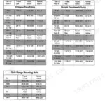
| Torque Charts and Schematics | 206-217 | Capscrew Diameter, Grade 5 Capscrew, Grade 8 Capscrew, Hardened Washer, Jic Swivel Nuts, Electrical Symbols |
Quick Reference Specifications
| Specification | Value | Page |
|---|---|---|
| Center post torque | 40 lb-ft (54 Nm) | p. 19 |
| Center bolt torque | 75 lb-ft (100 Nm) | p. 20 |
| Minimum cranking voltage | 18 volts | p. 62 |
| By-pass check valve opening pressure | 65 psi (450 kPa) | p. 68 |
| Swing Drifts-control in Neutral pressure | 1550 psi | p. 112 |
| Thrust plate clearance | 1/32 inch (0.8 mm) | p. 183 |
| Pocket seal length | 1/4 inch (63 mm) | p. 189 |
| total inside diameter of swivel housing | 4.253 ± .001 inch (108.03 ± .025mm) | p. 194 |
| chrome plating thickness to a side | .002 inch (.050mm) | p. 194 |
| Engine Cooling System Capacity | 32 L | p. 13 |
| Fuel Tank Capacity | 284 L | p. 13 |
| Hydraulic System Capacity | 246 L | p. 13 |