

Part of the Case Repair Manuals.
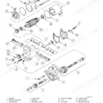
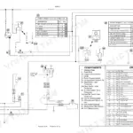
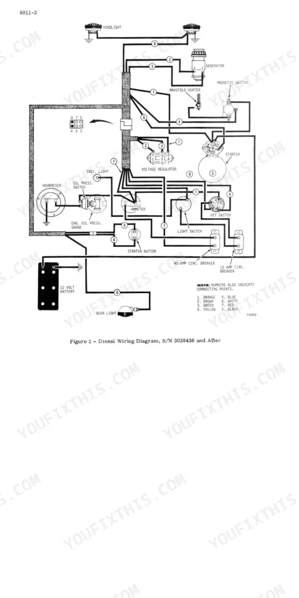
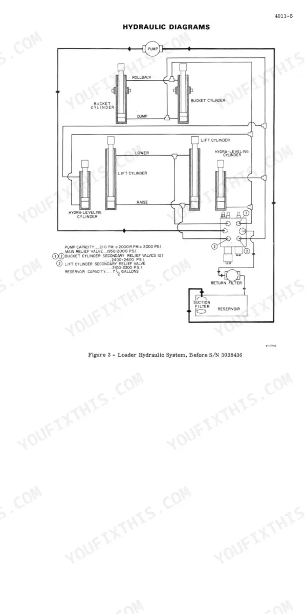
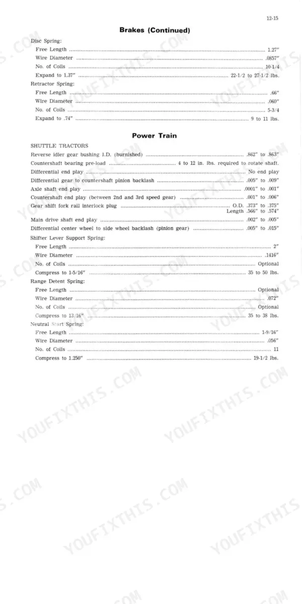
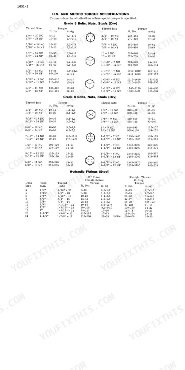
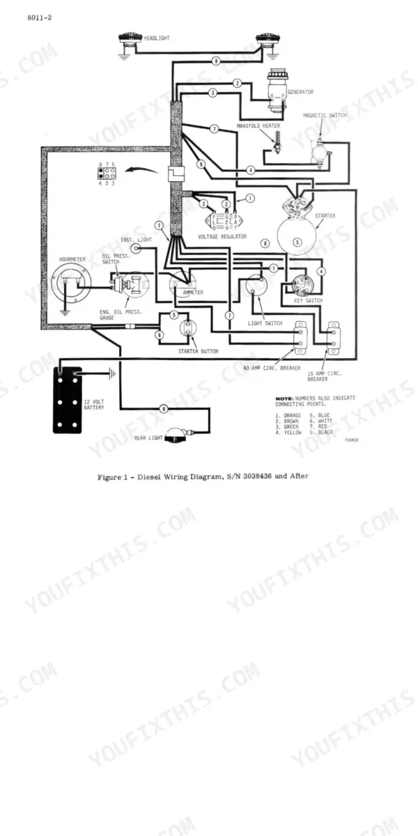
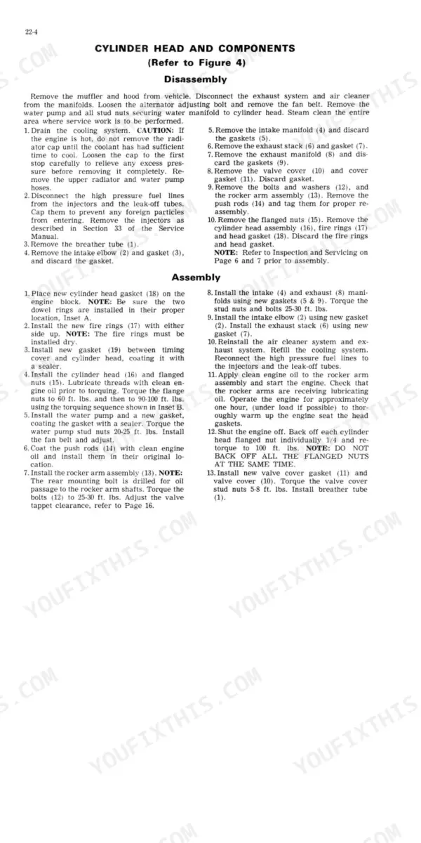
This 642-page J I Case 450 Crawler Service Manual (OEM #9-72332) walks you through every system on the dozer built around the 188 Diesel and 188G/159G/148G spark-ignition engines. Inside you get full wiring diagrams for the ignition, starter, and generator circuits, hydraulic schematics covering the loader, dozer, and backhoe control valves, plus a troubleshooting section for the transmission/converter hydraulic system using a flowmeter. You'll also find exploded views for the track and suspension system and a torque chart covering everything from sprocket mounting bolts to cylinder head fasteners. Set your suction line filter cleaning interval at 240 hours, and check battery specific gravity against 1.260 ± .005 before you condemn a weak charge. No more flipping through three different reprints looking for the right torque converter test. Bookmarked by section, searchable by keyword, and ready to pull up on your phone the second you're standing next to the machine.
What's Inside This Manual
| System | Pages | Key Topics |
|---|---|---|
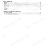
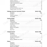
| Series - General | 3-27 | General Engine Specifications, Detailed Specifications, Maintenance and Lubrication, Torque Chart |
| Series - Engine | 28-98 | Cylinder Head and Valves 188 Diesel Engines, Engine Block Assemblies, Engine Removal Installation, Air Cleaner |
| Series - Fuel System | 99-132 | Fuel System and Filters, Roosa Master Db Fuel Injection Pump, Roosa Master Fuel Injector Pump 188 Diesel Engine, Throttle Linkage Adjustments |
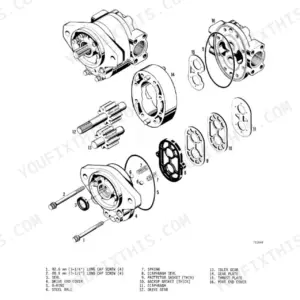
| Series - Hydraulics | 133-242 | Hydraulic Diagrams, Trouble Shooting, Pressure Checks, Equipment Pump D31254, D41390, Loader and Dozer Control Valves, Commercial Shearing Backhoe Control Valves |
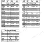
| Series - Track | 243-291 | Track and Suspension System, Torquing Procedure for Sprocket Mounting Bolts |
| Series - Power Train | 292-382 | Transmission and Final Drives, Trouble Shooting the Transmission/Converter Hydraulic System with a Flowmeter, Transmission/Converter Hydraulic System Diagram, Transmission Removal |
| Series - Brakes | 383-387 | Master Cylinders |
| Series - Electrical System | 388-455 | Wiring Diagrams, Trouble Shooting, Ignition System, Starter and Starter Solenoid, Generator and Voltage Regulator, Batteries |
| Series - Mounted Equipment | 456-642 | Loader, Dozers, Models 9 and 19 Gearmatic Winches, Ripper, Rollover Protection Structure, Models 26 and 26C Backhoe, Model 32 Backhoe, Model 33 Backhoe |
Quick Reference Specifications
| Specification | Value | Page |
|---|---|---|
| Torque converter reset procedure | Not found; removal and disassembly not recommended unless proven defective by Test No.4 in Section 6012, then replace parts as required. | p. 369 |
| Equipment hydraulic suction line filter cleaning interval | Every 240 hours | p. 23 |
| Torque converter suction line filter cleaning interval | every 600 hours of operation | p. 363 |
| Battery full charge specific gravity | 1.260 ± .005 | p. 448 |
| Generator belt tension (used belt) | 50-60 pounds | p. 445 |
| Brake single rib link nut torque | 11 ft. lbs. | p. 321 |
| Engine Crankcase Capacity (With Filter Change) | 6 Quarts | p. 3 |
| Engine Oil Pressure (Warm, Rated Engine Speed) | 50 to 70 Pounds | p. 3 |
| Fuel Injectors Opening Pressure (new) | 2750 to 2850 PSI | p. 16 |
| Cooling System Capacity (188D and 188G) | 16-1/2 U.S. Qts. | p. 14 |
| Engine Oil Filter Replacement Interval | Every 240 hours | p. 14 |
| Hydraulic Pump Output | 21 gpm at 2000 rpm at 1750 psi | p. 135 |