
Part of the Case Repair Manuals.
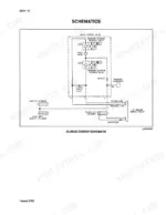
An hour from now you could have the flywheel brake off and this open on the bench: the Case 8570 service manual PDF, 496 factory pages covering the 8570 and 8570 Mid-Size baler. Electrical work carries its own full section: schematics that trace the baler control console and load control system connector by connector, with troubleshooting charts that take a symptom and run it back to a cause. Hydraulics get the same treatment. Set your timing and shear bolt sensor clearance at .020 to .030 IN (.50 to .75 mm); pull the plunger crank nuts at the gearbox output shaft to 325 LB-FT (440 N-m). Every hour that baler sits, the windrow keeps drying. Bookmarked and searchable by keyword, it is yours once, for as long as you own the machine.
What's Inside This Case 8570, 8570 Mid-Size Manual
| System | Pages | Key Topics |
|---|---|---|
| General | 3-46 | General Information, Safety Rules, Maintenance and Lubrication, Safety Decals |
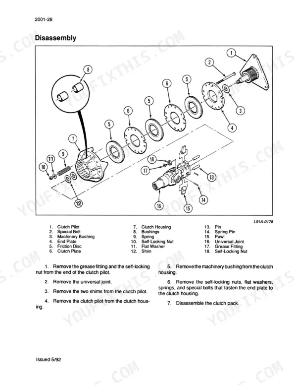
| Drive System | 47-154 | Connecting the Tractor, Implement Drive Line, Main Drive Shaft and Carrier Bearing, Main Drive Clutch, Flywheel, Flywheel Brake, And Gearbox |
| Pickup | 155-180 | Pickup Operation and Adjustments, Augers, Reel, Gauge Wheels |
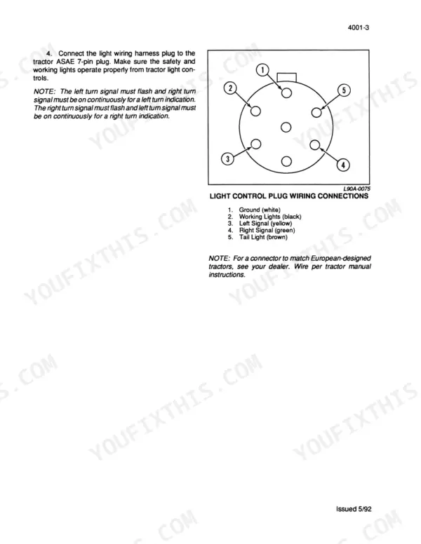
| Electrical System | 181-256 | Electrical Schematics and Troubleshooting, Baler Control Console, Load Control System |
| Feeder and Plunger | 257-322 | Packer, Stuffer and Charge Chamber, Plunger |
| Bale Wrapper | 323-414 | Knotter System |
| Mainframe, Bale Tension, and Wheels | 415-434 | Mainframe and Bale Tension, Axles, Wheels, And Tires |
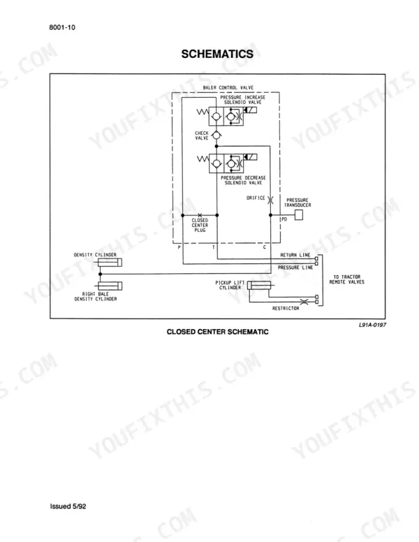
| Hydraulic System | 435-484 | Hydraulic System Operation, Baler Control Valve, Cylinders |
| Optional Equipment | 485-496 | Centralized Lubrication System |
Quick Reference Specifications
| Specification | Value | Page |
|---|---|---|
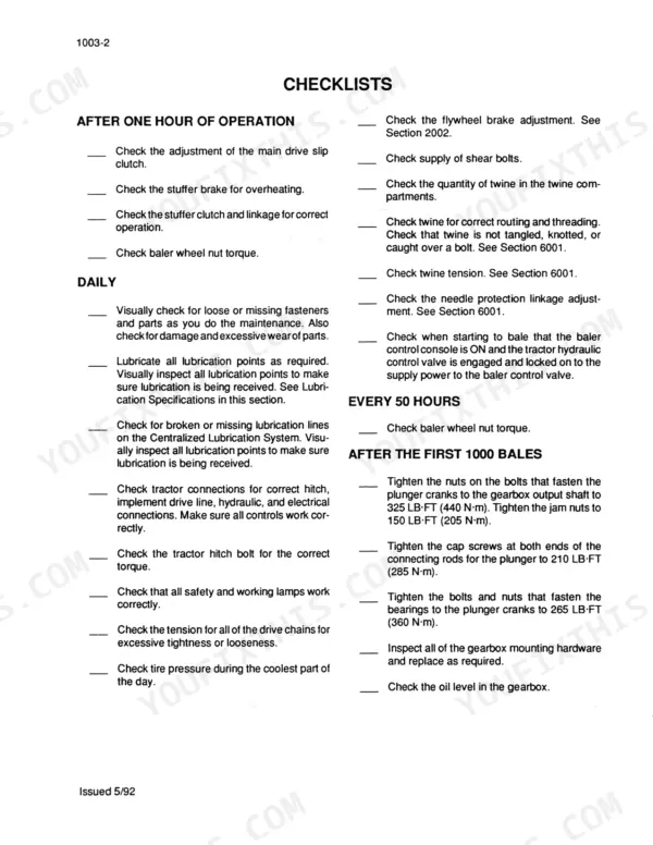
| Plunger crank to gearbox output shaft bolt torque | 325 LB-FT (440 N-m) | p. 18 |
| Plunger crank jam nut torque | 150 LB-FT (205 N-m) | p. 18 |
| Inductive sensor nut tightening torque | 7.5 LB-FT or 90 LB-IN (10 N-m) | p. 225 |
| Balers timing, shear bolt, and feeder clutch slip inductive sensor clearance | .020 to .030 IN (.50 to .75 mm) | p. 225 |
| Stake nut torque | 120 to 130 LB-FT (163 to 176 N-m) | p. 308 |
| Billhook holding cam spring pull to open billhook | 10 to 20 LBS (44 to 90 N) | p. 352 |
| Billhook holding cam spring pressure (if scale not available) | 1 to 3 LBS (.45 to 1.4 kg) | p. 352 |
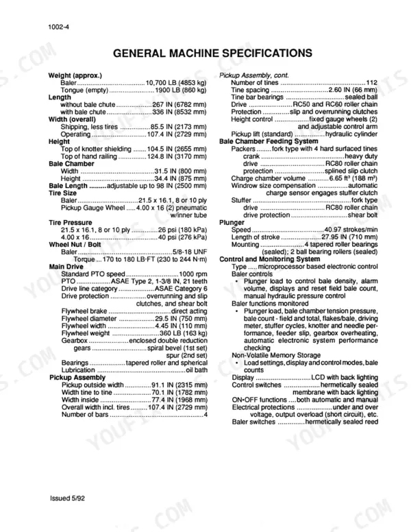
| Baler Weight (approx.) | 10,700 LB (4853 kg) | p. 12 |
| Standard PTO speed | 1000 rpm | p. 12 |
| Wheel Nut Torque | 170 to 180 LB-FT (230 to 244 N-m) | p. 12 |
| Gearbox Oil Capacity | 10 U.S. quarts (9.5 liters) | p. 23 |
| Plunger Stroke Length | 27.95 IN (710 mm) | p. 12 |
Case 8570, 8570 Mid-Size Common Problems This Manual Covers
Case 8570 baler monitor stays dead, console won't wake up when PTO is engaged
Check the inductive sensor on the right side of the gearbox first. Set clearance between the sensor face and the sprocket to .020 to .030 IN (.50 to .75 mm) per page 225, then tighten the mounting nuts to no more than 7.5 LB-FT (10 N-m). Measure sensor circuit resistance against the 3.1 to 3.2 k ohms value on page 224.
Manual Section: Electrical System p. 225Monitor loses the running signal intermittently and the console blanks out in the middle of a windrow
Trace the sensor harness back through the connectors shown in the wiring diagram, flexing each section by hand while you watch the console. Ohm the sensor circuit; it must read 3.1 to 3.2 k ohms. Reset the stuffer cycle sensor clearance to 0.010 to 0.020 IN (0.25 to 0.50 mm) if the gap has drifted.
Manual Section: Electrical System p. 224Flywheel shear bolts shearing repeatedly in heavy hay, plunger stops mid-stroke
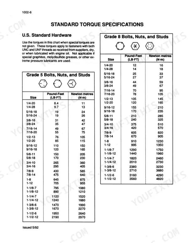
Check the main drive clutch before you blame the bolt itself. Verify the overrunning clutch lock nut is torqued to 125 LB-FT (170 N-m) as noted on page 72, then fit only a grade-correct replacement and tighten the shear bolt nut to 31 LB-FT (42 N-m). Ease your ground speed through thick windrows.
Manual Section: Flywheel Shear Bolt Troubleshooting p. 82Knotter miss-ties and dropped bales, twine tails hanging loose off the billhook
Inspect the billhook and holding cam before touching twine tension. Test the cam spring: it should take 10 to 20 LBS (44 to 90 N) of pull to open the billhook, per the setting on page 352. Then measure stripper arm travel past the billhook end, where 13/16 to 7/8 IN (20 to 22 mm) is normal.
Manual Section: Knotter System Troubleshooting p. 352Plunger knocking with ragged bale ends, hay not shearing clean at the chamber edge
Inspect the plunger knives and side rollers for wear. Set knife clearance at 1/8 to 3/16 IN (3 to 5 mm) and torque the knife bolts to 150 LB-FT (205 N-m) on page 310. With the plunger all the way to the rear of its stroke, set one side roller to 1/16 IN (1.5 mm) clearance from the side rail, per page 306. Do it before the next cutting is ready.
Manual Section: Feeder and Plunger p. 310Control console flags gearbox too hot after an hour of baling in hot weather
Drain and refill the gearbox to the full 10 U.S. quarts (9.5 liters) capacity listed on page 23, checking the level cold. Then verify the tractor holds PTO speed at 1000 rpm rather than lugging the baler down at low engine speed.
Manual Section: General p. 23Frequently Asked Questions
What is the wheel nut torque specification on a Case 8570, 8570 Mid-Size baler?
The wheel nuts for the baler must be tightened to a torque of 170 to 180 LB-FT (230 to 244 N-m). p. 12
What is the gearbox oil capacity and type for the 8570 baler?
The gearbox has a capacity of 10 U.S. quarts (9.5 liters) and requires Case IH 135 HEP Gear Lube 85W140. p. 23
How often should the gearbox oil be changed?
The gearbox oil should be drained and filled after the first 7500 bales, and the oil level should be checked every 2500 bales. p. 25
What is the correct spring length for the packer clutch?
The packer clutch springs should be adjusted to a length of 1-1/4 IN (32 mm). p. 260
What is the procedure to reset the field bale count?
To reset the field bale count, press and hold the RESET switch and the BALE COUNT switch simultaneously until the current count flashes three times and the display shows 0000. p. 199
Do I get instant access to this Case 8570 Service Manual?
You download the Service Manual yourself: 496 pages, searchable PDF, available immediately. Keep a copy on every device you use.
Am I able to print pages from this Case 8570 manual?
You can. Print the sections you want for your own use and keep the file as your backup.










Reviews
There are no reviews yet.