Part of the Case Repair Manuals.
From the diesel cylinder head and Powrcel fuel system through hydraulics, steering, transmission, brakes and planetary axles, this 510-page Case 1200 service manual PDF (OEM ID 9-75291) walks every system of the 1200 Traction King wheel tractor end to end. Electrical wiring diagrams sit with the specifications up front, and the hydraulic chapter takes the three-point hitch, hydraulic valve, pump and portable cylinder couplings apart in order. Transmission coverage runs through the Hi-Low shift rail, traction clutch and PTO drive, while H Series and Hydrovac brakes get separate sections. Torque the Powrcel clamp screw to 100 foot pounds. Coupling socket springs should test at 18-1/2 lbs. at a compressed height of 1-1/64". If your hydraulic check starts at the filter relief valve, its spring must compress to 1.656 inches for the valve to function properly. Bought once, the bookmarked, text-searchable file is yours to keep for this tractor, down to the differentials and drive shafts.
What's Inside This Case 1200 Traction King Manual
| System | Pages | Key Topics |
|---|---|---|
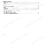
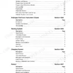
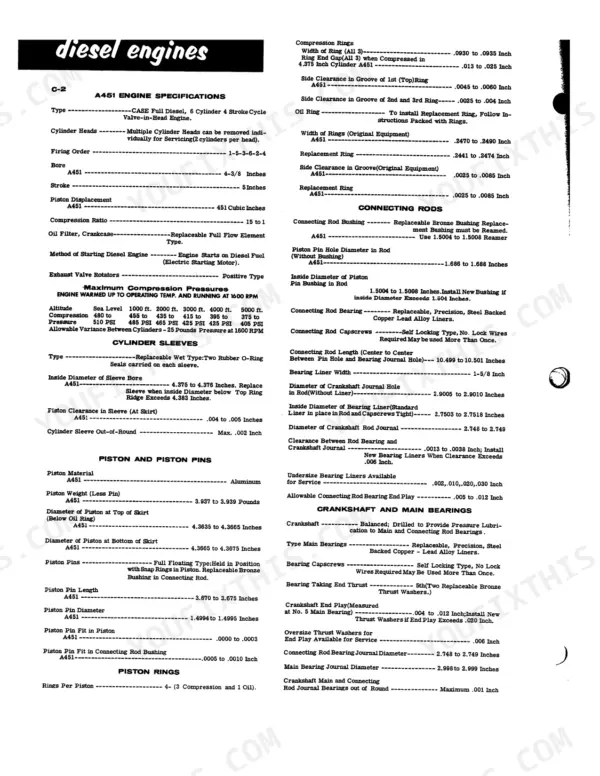
| I - Specifications | 5-30 | Engine Specifications, Cylinder Sleeves, Piston and Piston Pins, Connecting Rods, Crankshaft and Main Bearings, Valve System |
| II - Engine | 31-108 | Cylinder Head, Turbocharger, Assemblies Contained in Engine Block |
| III - Fuel System | 109-184 | Injectors, Pump, Powrcel |
| IV - Hydraulic System | 185-240 | Portable Cylinders, Couplings, Three-Point Hitch, Hydraulic Valve, Hydraulic Pump |
| V - Steering | 241-292 | Steering System, Power Steering Pump & Reservoir, Steering Pump |
| VI - Transmission | 293-404 | Forward and Reverse Control Cover, Output Shaft, PTO and Pump Drive, Input Shaft, Mainshaft and Hi-Low Shift Rail, Transmission Case and Oil Lines |
| VII - Brakes | 405-476 | H Series Brakes, Hydrovac Brakes |
| VIII - Planets, Axles, and Diff. | 477-510 | Planetaries and Axles, Planetaries and Axles Supplement 1, Differentials and Drive Shafts |
Quick Reference Specifications
| Specification | Value | Page |
|---|---|---|
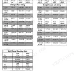
| Powrcel Clamp Screw torque | 100 foot pounds | p. 183 |
| Coupling socket spring pressure | 18-1/2 lbs. at a compressed height of 1-1/64" | p. 186 |
| Lowering poppet spring free length | 2.187 inches | p. 212 |
| Lowering poppet spring wire diameter | 0.080 inch | p. 212 |
| Pressure spring force at 2-1/16" compressed height | 170 - 185 lbs. | p. 360 |
| Required contact between lining and drum | 80% | p. 411 |
| Compression Pressure (1600 RPM) | 480 to 510 PSI | p. 10 |
| Fuel Injector Opening Pressure | 2200 to 2350 PSI | p. 108 |
| Hydraulic System Relief Valve Opening Pressure | 1500 PSI | p. 13 |
| Front Steering System Relief Valve Setting | 1375 to 1425 PSI | p. 243 |
| Rear Steering System Relief Valve Setting | 1425 to 1475 PSI | p. 243 |
| Power Steering Pump Relief Valve Setting | 1475 to 1525 PSI | p. 278 |
Case 1200 Traction King Common Problems This Manual Covers
Case 1200 Traction King battery terminals and cables corroded, batteries undercharged with very poor cranking speed
Clean the battery tray, holddown, terminals and cable ends with baking soda and water, then coat lightly with vaseline or cup grease (page 18). Keep sparks and open flame away and never lay a metal object on the battery. Following page 20, crank 15 seconds and compare battery and cranking motor voltage; over .5 volt difference means clean and tighten cables. Replace a battery reading under 9.5 volts at a 270 amp load.
Manual Section: Electrical System Troubleshooting p. 20Voltage regulator overcharging batteries, water consumption above 1 oz every 60 hours of operation
Inspect the case for leaks first; page 18 puts normal use near 1 oz per 60 hours. Hook up a 30 volt voltmeter and ammeter per page 23, since the manual forbids adjustments without test equipment. Turn the ignition off before touching the regulator and insulate your tool (page 22). Turn the slotted button toward minus; if two notches will not correct it, replace the regulator.
Manual Section: Electrical System Troubleshooting p. 23Alternator drive belts slipping with excessive wear, low or no alternator output
Check the alternator drive belts for looseness and wear every 60 hours, as page 25 calls for. Adjust each belt for 1/2 inch deflection, or 50 to 80 lbs. tension, between the fan and alternator pulleys, using a Belt Tension Gauge for the most accurate reading. Do not overtighten: too tight wears the alternator and water pump bearings and the fan belt.
Manual Section: Electrical System Troubleshooting p. 25Engine hard starting on the tractor with noticeable loss of power and excessive exhaust smoke
Clean carbon from the injector recess with the CD513 Carbon Reamer, then install the CD505 Adapter with the injector nozzle gasket in place (page 74). Keep your hands and arms out from in front of the injector nozzle; the fuel spray can puncture flesh and destroy tissue. Test compression at 1600 RPM and compare each cylinder against 480 to 510 PSI on page 10.
Manual Section: Engine Troubleshooting p. 74Faulty fuel injector isolated, showing poor spray pattern, leakage or incorrect opening pressure
Remove the injector and make sure the gasket comes out with it (page 117). On the test stand, close the pressure gauge valve and stroke the hand lever rapidly to purge air (page 122). Keep hands and arms clear of the nozzle; spray can puncture flesh. Check opening pressure against 2200 to 2350 PSI on page 108. Never force the injector back into the recess (page 118).
Manual Section: Fuel Injector Troubleshooting p. 122Hydrovac brake system giving poor braking with low vacuum reading at the hydrovac
Measure vacuum at the hydrovac and verify it reaches 20 inches of mercury, then check power assist hydraulic brake pressure against 1500 PSI, both listed on page 419. If either reading falls short, work through the Hydrovac Brake System Troubleshooting chart for low vacuum and poor brakes. Do not lose the hydrovac tag during servicing (page 420).
Manual Section: Hydrovac Brake System Troubleshooting p. 419Frequently Asked Questions
What is the correct valve tappet clearance for the A451 engine in the Case 1200?
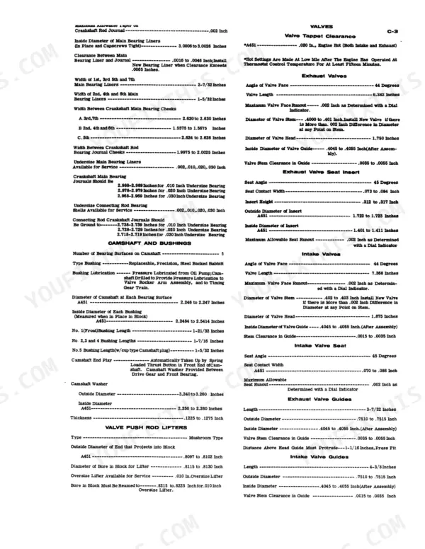
The valve tappet clearance for the A451 engine is .020 inch for both intake and exhaust valves. This setting must be made with the engine hot, at low idle, after the engine has operated at thermostat control temperature for at least fifteen minutes. p. 11
What is the tightening torque for the cylinder head bolts on the A451 engine in the Case 1200?
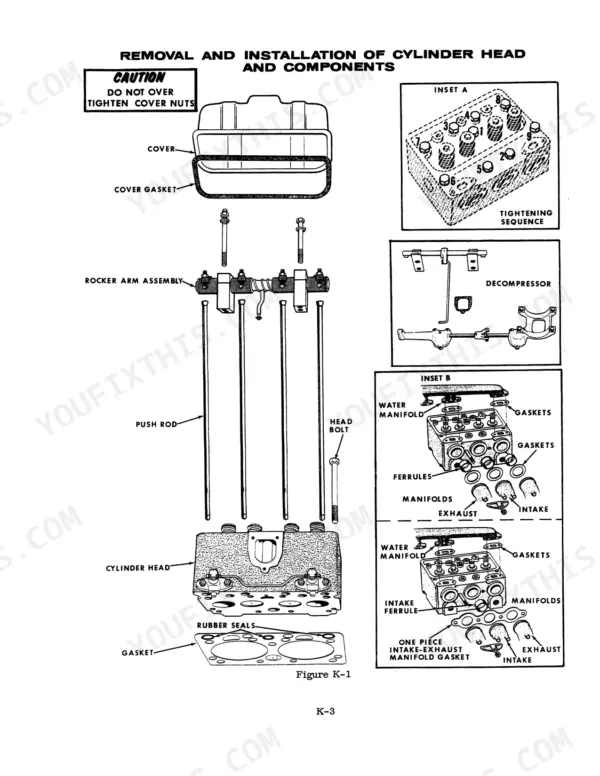
The tightening torque for the cylinder head bolts (Grade 8) on the A451 engine is 145 to 150 foot-pounds. These bolts are 9/16 inch in size with 18 threads per inch. p. 12
What is the required fuel injector opening pressure for the turbocharged engine on the Case 1200?
The fuel injector opening pressure for the turbocharged engine must be between 2200 PSI and 2350 PSI. This differs from the 1950 PSI to 2050 PSI specification listed for naturally aspirated engines. p. 108
How do I adjust the oil pump pressure relief valve?
The oil pump pressure relief valve is adjusted by turning the adjusting screw. One complete turn of the screw will make a difference of approximately 2 pounds per square inch of oil pressure. The screw should be turned in to increase pressure or out to decrease it, until the underside of the head is 1/2 inch from the boss on the pump body. p. 70
What exactly do I receive with this Case 1200 Service Manual?
Straight to your device: 510 pages of searchable Service Manual, downloadable the moment payment goes through.
Can I print just the pages I need from this Case 1200 manual?
Yes. It prints from any PDF reader, so run off the pages you need for your own repair work.
Can I trace circuits with this Case 1200 manual?
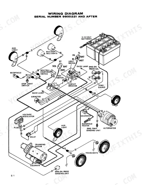
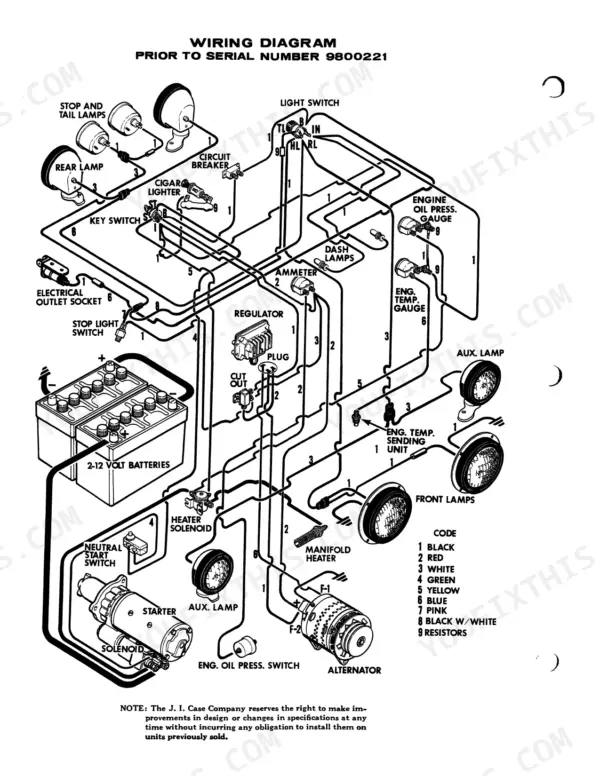
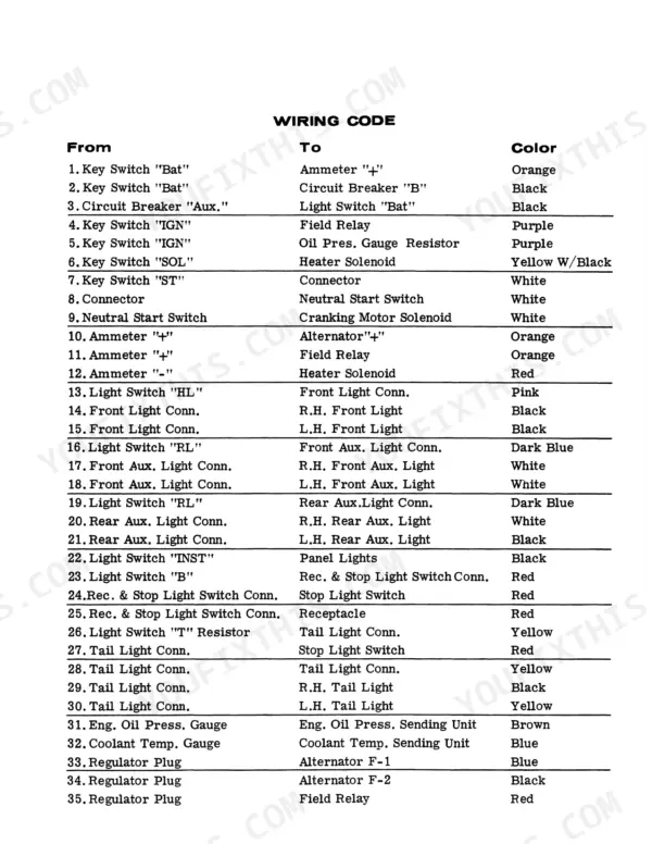
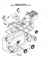
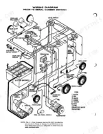
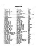
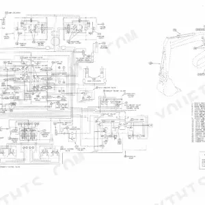
Yes. The Case 1200 Traction King Service Manual carries the electrical wiring diagrams. Page 6 carries one of them.