Part of the Case Repair Manuals.
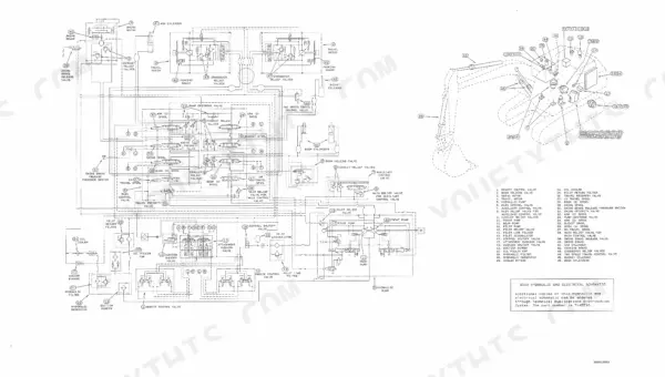
Rebuilding a Case 9010 excavator to factory spec is the job these 534 pages are built for, and this Case 9010 service manual pdf (OEM ID 7-45720) runs from engine removal and the Bosch injection pump through the track rollers, final drive and turntable bearing. Foldout hydraulic and electrical schematics trace the complete circuits, while the hydraulics section sets out specifications, troubleshooting and pressure checks before moving into the main pump, main control valve, swing reduction gear box and cylinders. Track system troubleshooting and a turbocharger failure analysis chapter cover diagnosis. Plan for a 117 lb (53 kg) lift when the radiator comes out, and torque injector retaining nuts to 55 to 65 Nm. If you are tracing the pilot control circuit from its pump to the remote control and solenoid valves, the hydraulic schematic shows how those lines connect. Bookmarked and text-searchable, the PDF travels with you to wherever your 9010 is working.
What's Inside This Case 9010 Manual
| System | Pages | Key Topics |
|---|---|---|
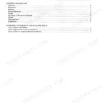
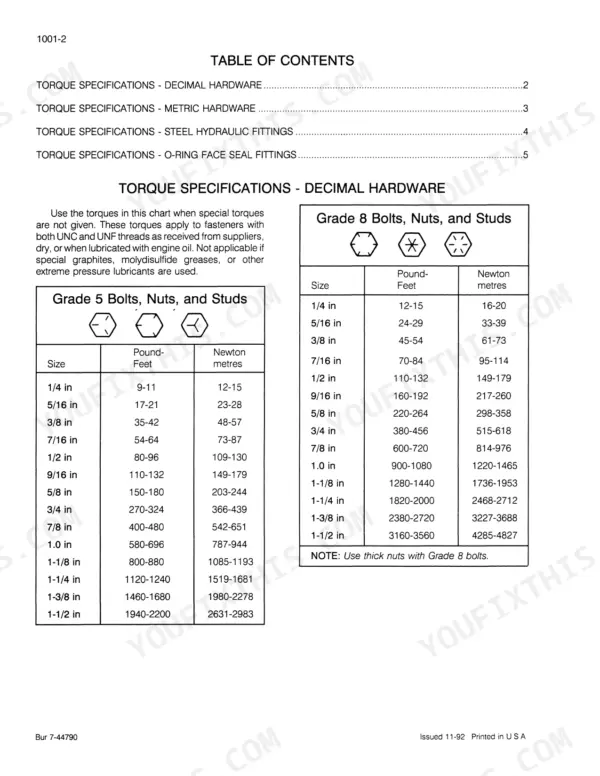
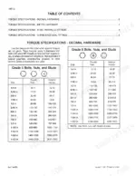
| General | 3-16 | Section Index - General (Standard Torque Specifications for 9000 Series Excavators, Fluids and Lubricants) |
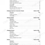
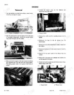
| Engines | 17-222 | Section Index - Engines (Engine Removal and Installation, Radiator Removal and Installation, Engine Specification Details) |
| Fuel System | 223-266 | Section Index - Fuel System (System and Filters, Injectors, Injection Pump) |
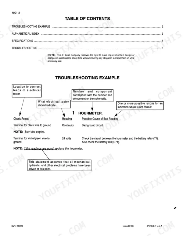
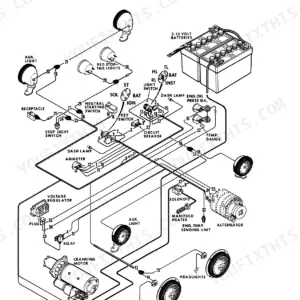
| Electrical | 267-352 | Section Index - Electrical (Electrical Specifications and Troubleshooting, Electric Schematic Foldout, Batteries, Systems Display Panel, Starter and Starter Solenoid, Alternator) |
| Tracks | 353-382 | Section Index - Tracks (Troubleshooting the Track System, Rollers, And Idlers) |
| Power Train | 383-390 | Section Index - Power Train (Troubleshooting, Drive Motor and Final Drive Transmission) |
| Hydraulics | 391-506 | Section Index - Hydraulics (Cleaning the Hydraulic System, Hydraulic Specifications, Troubleshooting) |
| Mounted Equipment | 507-532 | Section Index - Mounted Equipment (Pedals and Levers, Turntable Bearing, Boom and Arm, Seat and Seat Belts, Electric and Hydraulic Schematic Foldout) |
| 7-45710 Schematics | 533-534 | Hydraulic Schematic, Electrical Schematic |
Quick Reference Specifications
| Specification | Value | Page |
|---|---|---|
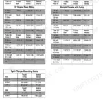
| 37 Degree Flare Fittings 1/4 in Tube OD Torque | 6-12 Pound-Feet (8-16 Newton metres) | p. 8 |
| 37 Degree Flare Fittings 5/16 in Tube OD Torque | 8-16 Pound-Feet (11-22 Newton metres) | p. 8 |
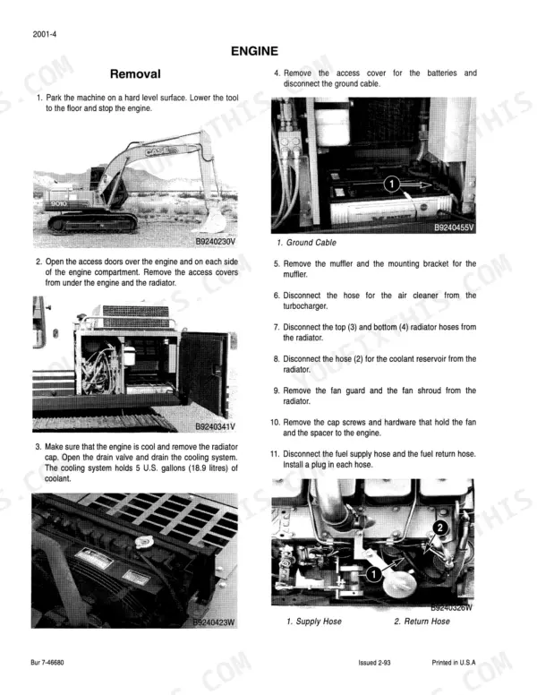
| Weight of the radiator | 117 pounds (53 kg) | p. 30 |
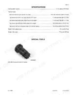
| Injector Retaining Nut Torque | 55 to 65 Nm | p. 232 |
| Leak Off Bolt Torque | 8 Nm | p. 232 |
| Weight of the drive motor and final drive transmission | 309 pounds (140 kg) | p. 386 |
| Cap screws that hold the sprocket to the final drive transmission torque | 197 to 230 pound-feet (267 to 312 Nm) | p. 386 |
| Main Relief Valve Pressure | 4200 to 4350 psi (28 959 to 29 993 kPa, 290 to 300 bar) | p. 401 |
| Crossover Relief Valve Pressure (RH Travel Circuit) | 4200 to 4350 psi (28 959 to 29 993 kPa, 290 to 300 bar) | p. 401 |
| Cap screws that hold the hydraulic pump to the flywheel housing torque | 46 to 54 pound-feet (62 to 73 Nm) | p. 435 |
| Weight of the hydraulic pump | 201 pounds (91 kg) | p. 435 |
| Hydraulic reservoir capacity | 21.9 U.S. gallons (83 litres) | p. 435 |
Case 9010 Common Problems This Manual Covers
Case 9010 rear pump circuits problem: auxiliary, LH travel, boom, swing, and arm functions all affected
Clean all dirt and debris from around the auxiliary control valve first, as page 405 directs. This matters most if you rarely run the auxiliary circuit. Then run the front and rear pump tests. Before you remove the hydraulic reservoir cover, slowly loosen the fill cap to relieve air pressure, per the warning on page 413.
Manual Section: Hydraulic System Troubleshooting p. 405Main relief valve or boom, arm, bucket circuit relief pressure out of spec during hydraulic pressure check
Test the main relief valve first, then the circuit relief valves, using the Relief Valve Tests procedure. Compare your gauge readings against page 401. Main relief and travel crossover reliefs should read 4200 to 4350 psi (290 to 300 bar). Arm, bucket, and boom up circuits should read 3625 to 3775 psi (250 to 260 bar). Boom down should read 2925 to 3075 psi (202 to 212 bar).
Manual Section: Relief Valve Tests p. 401Accumulator will not let boom and arm lower to the ground after the engine stops
Check the accumulator following page 425. Turn the key switch ON but do not start the engine, then try to lower the boom and arm. The accumulator holds highly pressurized nitrogen gas. If it does not work correctly, replace the accumulator. Do not try to repair it, because the manual warns this can cause injury or death.
Manual Section: Accumulator Check p. 425Control valve spools do not return to neutral on the main control valve
Test pilot pressure at the ends of the spools with the Pilot Pressure Test procedure. To clean the hydraulic system, follow page 397: retract all cylinder rods, then change the hydraulic oil and filters. If retracting the rods raises the attachment, block it in place first. Make sure no attachment can fall before you disconnect any hydraulic lines. Refill to the 21.9 U.S. gallon (83 litre) reservoir capacity listed on page 13.
Manual Section: Cleaning the Hydraulic System p. 395Undercarriage track adjustment trouble: track tension will not set correctly at the recoil spring and idler
Inspect the track adjustment, recoil spring, idler wheel, and rollers using the Track System Troubleshooting chart. When you release tension at the track adjustment cylinder, do not remove the check valve. Page 367 warns that the grease inside is under high pressure. Check the sprocket, pins, and bushings for wear while you have the track slack.
Manual Section: Track System TroubleshootingStarter cranks slowly or will not crank the engine on battery power
Test the batteries before condemning the starter, using the electrical troubleshooting steps. Never apply a load for more than 15 seconds at a time (page 320). Disconnect the ground cable first and connect it last. Keep sparks away from charging batteries (page 306). Never charge a frozen battery (page 310). Do not crank longer than 30 seconds (page 216).
Manual Section: Electrical TroubleshootingFrequently Asked Questions
What are the hydraulic pressure specifications for a Case 9010?
The main relief valve for the main control valve is set to 4200 to 4350 psi (28 959 to 29 993 kPa, 290 to 300 bar). The relief valve for the pilot pump is set to 570 to 640 psi (3930 to 4413 kPa, 39 to 44 bar). p. 401
What are the torque specifications for Case 9010 engine mounts and hydraulic pump bolts?
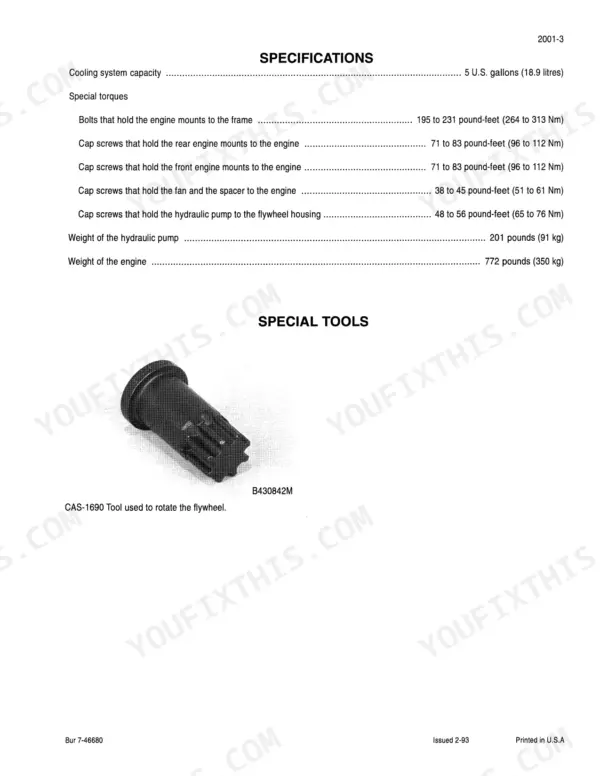
The bolts that hold the engine mounts to the frame must be tightened to 195 to 231 pound-feet (264 to 313 Nm). The cap screws that hold the hydraulic pump to the flywheel housing must be tightened to 48 to 56 pound-feet (65 to 76 Nm). p. 21
How do you bleed the cooling system on a Case 9010?
To bleed the cooling system, fill the radiator and coolant reservoir with a mixture of 55% ethylene glycol and 45% water. Run the engine at high idle until the water temperature gauge indicates normal operating temperature (4th or 5th amber bar), then open the heater shutoff valve. Continue running until the last amber bar illuminates, then let the engine cool before topping off the coolant. p. 26
What is the cylinder head bolt torque specification for the 4-390 diesel engine in the Case 9010?
For the 4-390 diesel engine, the short cylinder head bolts are torqued to 90 Nm plus 90 degrees, and the long bolts are torqued to 120 Nm plus 90 degrees. p. 46
What is the engine oil capacity for the 9010 excavator?
The engine oil capacity for the 9010 excavator is 11.6 U.S. quarts (11 litres) with a filter change. p. 13
How quickly can I access this Case 9010 manual after buying?
Immediate download of the complete 534-page searchable Service Manual. Access it on any device, from a laptop at your desk to a phone in the field.
Can I print this Case 9010 manual?
Yes. Print a chapter or just the pages for the job at hand, for use in your own shop. Any home or office printer works.