Part of the Case Repair Manuals.
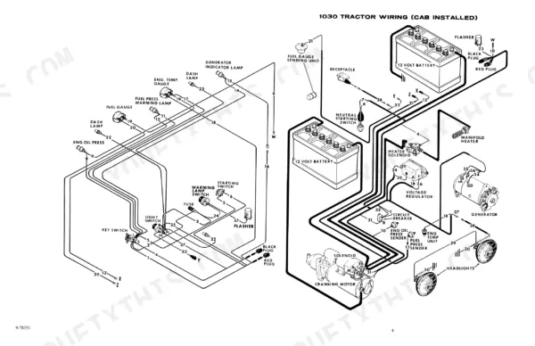
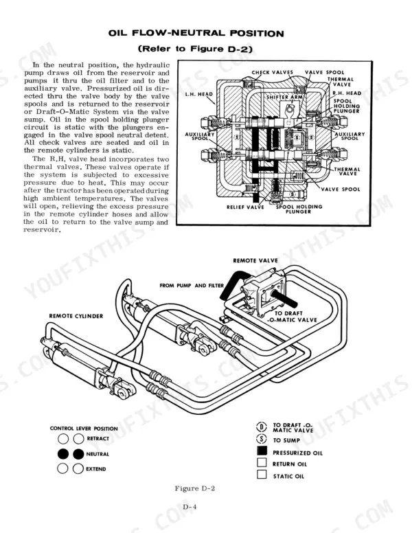
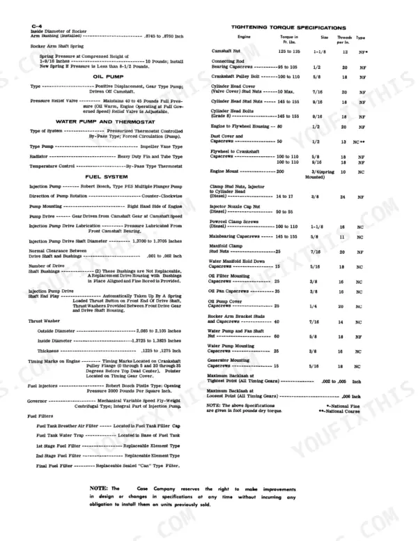
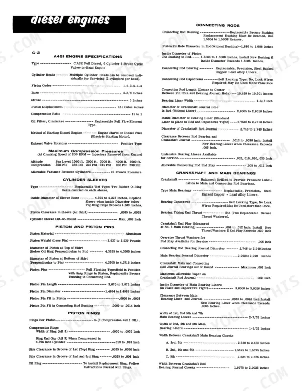
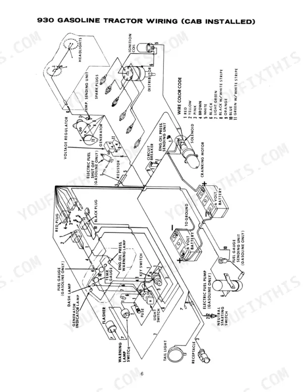
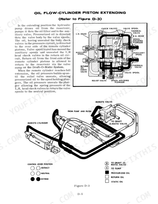
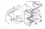
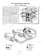
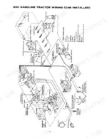
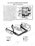
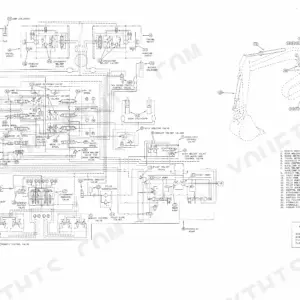
Engine, Powrcel fuel system, hydraulics, steering and transmission run end to end through this 300-page Case 930 service manual PDF (OEM ID 9-76931), written for the 930 and 1030 tractors. Wiring diagrams trace the electrical circuits, while hydraulic schematics lay out the auxiliary valve, hydraulic pump and Draft-O-Matic system so you can follow oil routing through the draft control circuit. Steering coverage runs from the front axle to the power steering pump, and the transmission chapters take in the power take-off, traction foot clutch, differential, final drive and differential brakes. Set piston clearance in the sleeve at .0035 to .0055 inch at the skirt, then draw cylinder head stud nuts to 145 to 155 ft. lbs. Suspect a cylinder sleeve worn out of round? The maximum allowed is .002 inch. Bookmarks and a searchable text layer jump you straight to the Draft-O-Matic or PTO pages.
What's Inside This Case 1030, 930 Manual
| System | Pages | Key Topics |
|---|---|---|
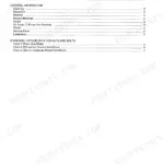
| Table of Content | 3-4 | |
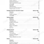
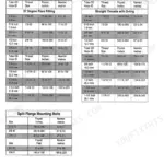
| Specifications | 5-32 | Engine Specifications, Cylinder Sleeves, Piston and Piston Pins, Piston Rings, Connecting Rods, Crankshaft and Main Bearings |
| Engine | 33-101 | Cylinder Head, Assemblies Contained in Engine Block, Water Pump |
| Fuel System | 102-144 | Injectors, Pump, Powrcel |
| Hydraulic System | 145-210 | Portable Cylinders, Couplings, Auxiliary Valve, Hydraulic Pump, Draft-O-Matic System |
| Steering | 211-244 | Front Axle, Power Steering System, Power Steering Pump |
| Transmission | 245-300 | Power Take-Off, Traction Foot Clutch, Differential, Final Drive, Differential Brakes |
Quick Reference Specifications
| Specification | Value | Page |
|---|---|---|
| Cylinder Head Stud Nuts Torque | 145 to 155 ft. lbs. | p. 8 |
| Cylinder Head Bolts (Grade 8) Torque | 145 to 155 ft. lbs. | p. 8 |
| Inside Diameter of Sleeve Bore | 4.375 to 4.376 inches | p. 6 |
| Piston Clearance in Sleeve (At Skirt) | .0035 to .0055 inch | p. 6 |
| Connecting Rod Bearing Capscrews Torque | 95 to 105 ft. lbs. | p. 8 |
| Clearance Between Rod Bearing and Crankshaft Journal | .0013 to .0038 inch | p. 6 |
| Relief Valve Cracking Pressure | 1700 to 1900 PSI | p. 171 |
| Relief Valve Setting | 1900 to 2050 PSI | p. 171 |
| Piston Pin Diameter | 1.4994 to 1.4995 inches | p. 6 |
| Cylinder Head Stud Nut Torque | 145 to 155 ft. lbs. | p. 8 |
| Main Bearing Capscrew Torque | 145 to 155 ft. lbs. | p. 8 |
| Connecting Rod Bearing Capscrew Torque | 95 to 105 ft. lbs. | p. 8 |
Case 1030, 930 Common Problems This Manual Covers
Case 1030 and 930 battery terminals and cables corroded, engine cranking very slowly
Clean terminals, cable ends and battery tray with baking soda and water per page 20, keeping sparks and flame away and never laying metal tools on the battery. Pull the fuel stop lever or throttle to off, crank 15 seconds, and compare battery and cranking motor voltage per page 22. Over .5 volt difference means clean and tighten connections. Rest the cranking motor two minutes after 30 seconds of cranking (page 27).
Manual Section: Battery Service and Inspection p. 20Battery using more than about 1 oz of water every 60 hours of operation
Inspect the battery case first: a cracked or leaking case means replace the battery, while leaking top sealing compound can be resealed (page 20). If the case is tight, the regulator is overcharging. Check regulator output voltage against the ambient temperature chart on page 23, for example 14.3 to 15.3 volts at 85°F. Never attempt even minor electrical adjustments without proper test equipment; major adjustments go to an authorized electrical service station.
Manual Section: Regulator and Generator Checks p. 23Generator drive belts slipping or oily commutator, giving low or no generator output
Check each generator drive belt for looseness and wear, then set it to 1/2 inch deflection (60 pounds) between the fan and generator pulley per page 25, ideally with a belt tension gauge. Too tight wears the generator and water pump bearings. Lubricate oil cup generators with only 6 to 8 drops of medium engine oil every 60 hours, never while running; excess oil on the commutator kills output.
Manual Section: Regulator and Generator Checks p. 25Batteries failing to hold charge with cell specific gravity varying by .025 or more
Test each cell with a hydrometer held vertically at eye level, correcting .004 points per 10°F away from 80°F (page 21); a .025 spread between cells means replace. Cross-check cell voltage on page 22: below 1.95 volts or .05 volt variation means replace. Bench load at 270 amps for 15 seconds; under 9.5 volts, replace. Keep sparks and flame away and wash any acid contact with baking soda and water (page 20).
Manual Section: Battery Service and Inspection p. 21Cylinder head off for gasket replacement, unsure which fire ring gasket fits sleeve protrusion
Drain the cooling system and steam clean the engine before pulling the heads (page 34). Clean the block top and sleeve flanges, stone off burrs, clamp each sleeve with hold-down capscrews torqued to 50 foot pounds, then measure protrusion with a dial indicator or depth micrometer per page 36. Use the thicker .004 inch blue-striped fire ring if the chart calls for it. Torque head stud nuts to 145 to 155 ft. lbs. (page 8).
Manual Section: Cylinder Head and Valve Service p. 36Diesel engine running rough, suspect a faulty injector with poor spray pattern or leakage
Check each cylinder to isolate the faulty injector, then remove it making sure the gasket comes out with it (page 109); never force an injector back into the head (page 110). Test leakage and spray pattern on a test stand, keeping hands and arms clear of the nozzle because the spray can puncture flesh (page 104). Clean without abrasives or hard tools (page 120), and run only diesel fuel meeting CASE specifications (page 116).
Manual Section: Fuel Injector Service p. 109Frequently Asked Questions
How do I troubleshoot a Case 1030 that loses power or starves for diesel under load?
If the engine loses power or starves under load, check for a plugged air cleaner, fuel tank breather, or fuel filters. Also, ensure the fuel injection pump is timed correctly as described in the Fuel Injection System section. If the engine is misfiring, isolate the faulty injector by loosening the high-pressure fuel line fitting on each injector while the engine is running to see which one least affects engine speed. p. 139
What are the replacement specifications for the cylinder head gasket on a Case 1030, 930 tractor?
When installing a standard head gasket, ensure the copper side or the side with the case part number is facing up. If installing a fire ring head gasket, check the cylinder sleeve protrusion to determine if a standard or a thicker .004 inch fire ring is required. The thicker fire ring is identified by a blue marking stripe. p. 34
What is the correct tightening torque for the cylinder head bolts on a Case 1030, 930 tractor?
The cylinder head bolts (Grade 8) must be tightened to 145 to 155 foot-pounds. When installing the cylinder head, use a three-step torquing sequence of 50 foot-pounds, 100 foot-pounds, and finally 150 foot-pounds. p. 8
What is the correct valve tappet clearance for the A451 diesel engine in the Case 1030, 930?
The valve tappet clearance for both intake and exhaust valves is 0.025 inch when the engine is cold. When the engine is hot, the clearance is 0.020 inch. Hot settings must be made at low idle after the engine has operated at thermostat control temperature for at least fifteen minutes. p. 7
How do I adjust the power steering drive belt tension?
The power steering drive belt should have no visible deflection under normal finger pressure, or it should measure 75 pounds when checked with a belt tension gauge between the crankshaft and power steering pump pulley. To adjust, loosen the capscrews on the pump mounting clamp straps and move the pump assembly upward. p. 235
How will I receive this Case 930 Service Manual?
Straight to your device: 300 pages of searchable Service Manual, downloadable the moment payment goes through.
Can I print a copy of this Case 930 Service Manual for the shop?
Yes. Print the sections you need to take out to the shop for your own use. Standard letter or A4 paper works.