

Part of the Case Repair Manuals.
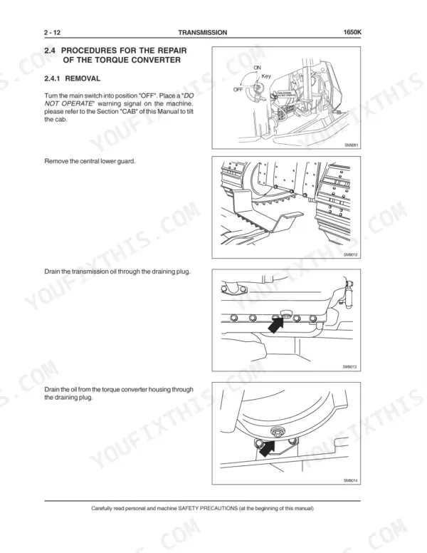
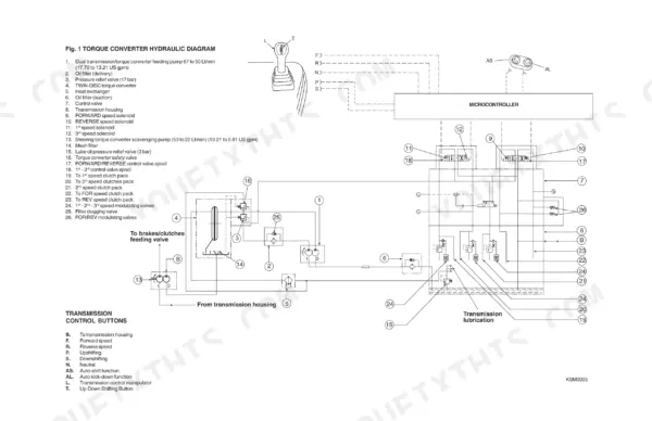
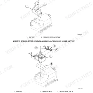
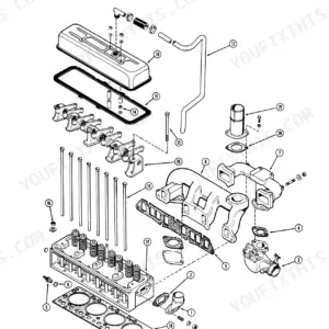
Looking for a Case 1650K service manual PDF with real factory data? All 319 pages of this workshop manual (OEM #6-46470) cover the Case 1650K Crawler Dozer, from the engine and torque converter through final drives, undercarriage, and dozer hydraulics. You get hydraulic schematics for the blade and ripper circuit, wiring diagrams for the electrical system, and page after page of exploded views spanning the transmission, brakes, and steering differential. Open the transmission section and you're straight into clutch, modulating valve, and torque converter rebuild procedures. Tighten the torque converter securing screws to 6.8 to 7.4 daNm (50.15 to 54.58 ft lbs), and hold spool-to-seat clearance at 0.22 to 0.25 mm. Your dozer is down and daylight is burning. Bookmarked PDF that opens on any device; carry your tablet to the machine and start wrenching.
What's Inside This Case 1650K Manual
| System | Pages | Key Topics |
|---|---|---|
| Generalities | 6-45 | Safety Rules, Table of Capacities, Table of Centre of Gravity, Main Dimensions, Tables of Technical Data, Check Data on the Machine, Equipment Manoeuvre Times, Table of Weights |
| Engine | 46-57 | Engine Main Specifications, Engine Identification, Design Features, Serviceability, Securing the Engine to the Frame |
| Transmission | 58-125 | Torque Converter, Transmission Housing, Transmission Clutch, Modulating Valves, Pressure Relief Valve, Oil Filters |
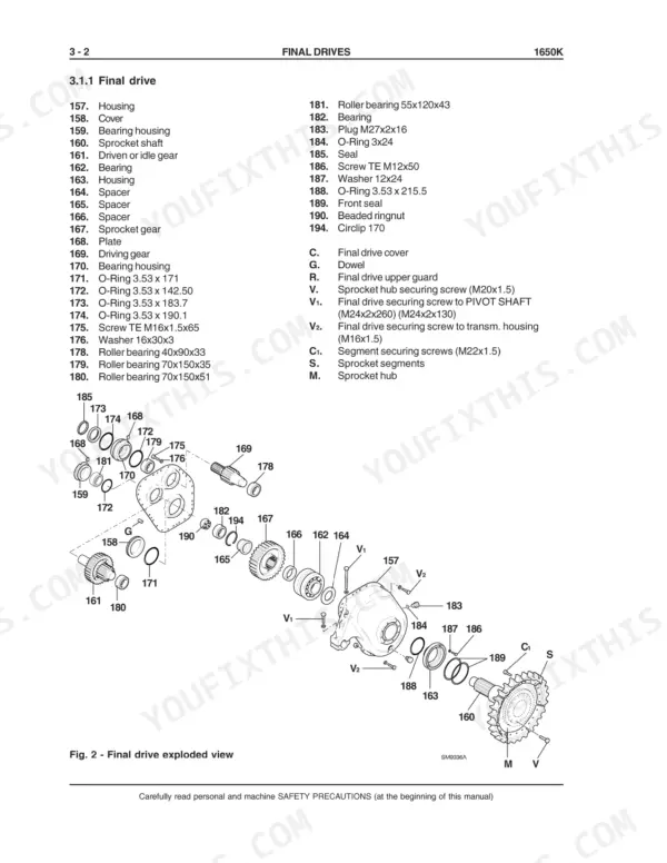
| Final Drives | 126-149 | Final Drive Housing, Sprocket Shaft, Driven Gear, Driving Gear Shaft, Front Seals, Final Drive Assembly |
| Brakes and Steering Differential | 150-236 | Brakes Hydraulic Circuit, Brake Power Pump, Brake Pedal Valve, Steering Side Group, Bevel Gear Set, Brake Group |
| Undercarriage | 237-268 | Track Frames, Track Chain, Idler, Track Chain Support Rollers, Bottom Rollers, Track Tensioner Device |
| Dozer Equipment Hydraulic System | 269-295 | Hydraulic Control Valve, Power Hydraulic Pump, Blade Lifting Cylinder, Blade Tilt Cylinder, Ripper Cylinder, Push Beams |
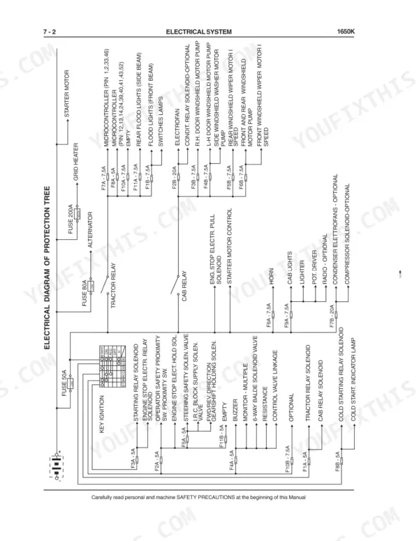
| Electrical System | 296-319 | Fuses, Main Switch, Starter Motor, Instrument Panel, Monitor Senders, Relay Group |
Quick Reference Specifications
| Specification | Value | Page |
|---|---|---|
| torque for torque converter securing screws | 6.8 to 7.4 daNm (50.15 to 54.58 ft lbs) | p. 73 |
| Nominal output of transmission feeding section | 67 Lt/min (17.7 US gpm) | p. 123 |
| Nominal output of torque converter feeding section | 50 Lt/min (13.2 US gpm) | p. 123 |
| Clearance between seat and spool (transmission clutches) | 0.22 to 0.25 mm (0.008 to 0.009 in) | p. 117 |
| Clearance between plunger and seat (forward/reverse modulating valves) | 0.020 to 0.054 mm (0.001 to 0.002 in) | p. 121 |
| Self-locking screws (C1) securing the bush housings M10x1.25 | 7.8 daNm (57.525 ft lbs) | p. 261 |
| Radiator cap pressure | 1.0 bar | p. 23 |
Case 1650K Common Problems This Manual Covers
Case 1650K loses all drive and hydraulics at once while the engine still runs normally
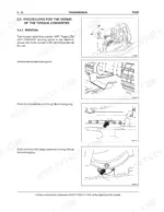
Remove the torque converter access cover and inspect the flexplate for cracks or broken mounting bolts. Replace a cracked flexplate and clean all debris out of the bellhousing before reassembly. Reinstall the torque converter securing screws per the procedure on page 73, torquing them to 6.8 to 7.4 daNm (50.15 to 54.58 ft lbs).
Manual Section: Transmission p. 73Transmission won't engage right away when cold, drive comes in after several minutes of idling
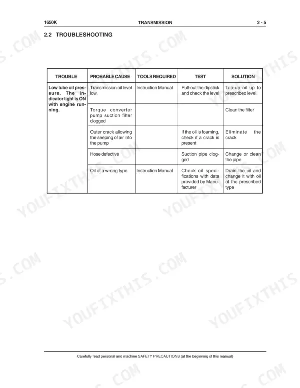
Check the transmission oil level first, then tighten every suction hose clamp and inspect the suction lines for cracks letting the pump draw air. Test charge pump delivery against the 67 Lt/min (17.7 US gpm) spec on page 123; replace the pump if output falls short.
Manual Section: Transmission Troubleshooting p. 123One track creeps in neutral or the machine pulls to one side under load
Verify the steering linkage adjustment first, then check clutch pack apply pressure at the test ports using the machine movement charts. Pull the clutch pack and look for a broken plate holding it partially engaged. The transmission clutch table on page 117 calls for 0.22 to 0.25 mm (0.008 to 0.009 in) between seat and spool; if you go into the forward/reverse modulating valves, page 121 calls for 0.020 to 0.054 mm (0.001 to 0.002 in) between plunger and seat.
Manual Section: Transmission Troubleshooting p. 117Engine runs hot or high temperature alarm comes on during heavy pushing
Clean the radiator core with compressed air blown from the fan side, then check the shroud for cracks or gaps that let hot air recirculate. Pressure test the radiator cap; it must hold 1.0 bar per the spec on page 23. Verify the fan is installed facing the correct direction and ease off the load if temperature stays high.
Manual Section: Generalities p. 23Track chain hangs loose and slaps the frame, or runs tight and wears fast
Measure track sag with the machine on flat ground and adjust the grease tensioner following the undercarriage procedures starting on page 237. Inspect the tensioner relief valve if the chain will not hold adjustment. If you pull the bottom rollers during the repair, torque the M10x1.25 self-locking bush housing screws to 7.8 daNm (57.525 ft lbs), spec on page 261.
Manual Section: Undercarriage p. 237Frequently Asked Questions
What do Case 1650K error codes mean?
The 1650K shows a five-character fault code. The first digit is the speed engaged, the second character is the letter 'E' marking a failure, and the last three digits identify the fault itself. Code 004 is a Forward speed 'F' solenoid failure and 008 is a Reverse speed 'R' solenoid failure; the full list is Table 1 on page 163, in the brakes and transmission control section. p. 163
What are the replacement specifications for the transmission charge pump?
The transmission feeding pump has a nominal output of 67 Lt/min (17.7 US gpm) at maximum speed, while the torque converter feeding section has a nominal output of 50 Lt/min (13.2 US gpm). The maximum speed for these twin gear pumps is 2650 rpm. p. 123
What is the specified torque for the final drive housing securing screws?
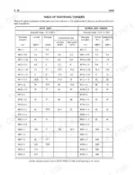
Page 140 says to fit the eight M12x50 securing screws and tighten them to the torque given in the Table of Tightening Torques in Section 0, printed on page 45. For class 10.9 screws that table lists M12x1.25 at 12.7 daNm (93.7 ft lbs) normal and 13.9 daNm (102.5 ft lbs) self-locking, and M12x1.75 at 11 daNm (81.1 ft lbs) normal and 12 daNm (88.5 ft lbs) self-locking, so check the pitch of your screws before you torque them. p. 140
What is the engine valve clearance for the 6BT 5.9 engine?
For the Cummins 6BT 5.9 engine, the intake valve clearance is 0.25 mm (0.009 in) and the exhaust valve clearance is 0.51 mm (0.020 in). p. 48
What is the cooling system capacity for the 1650K?
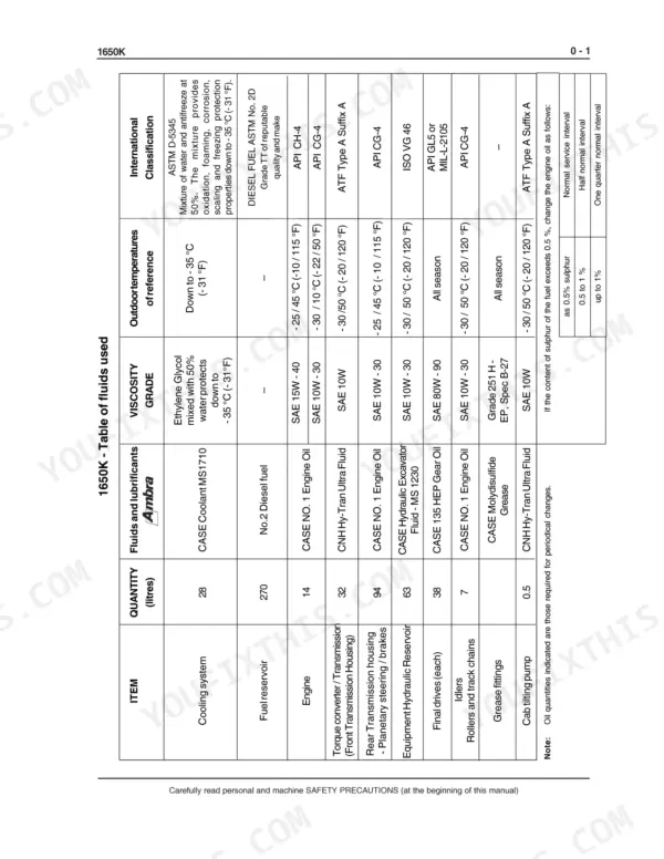
The table of fluids on page 18 lists the machine cooling system at 28 litres. The engine main specifications on page 48 give the Cummins 6BT 5.9 coolant capacity as 9 litres (2.38 US Gal). p. 18
How is this Case 1650K Service Manual delivered?
Instant PDF download. You get the full 319-page scanned Service Manual immediately after payment. Open it on your laptop, tablet, or phone right in the shop.
Is printing allowed for this Case 1650K Service Manual?
Yes. Print the pages you need for the job in your own shop, and bin them when they get greasy.









Reviews
There are no reviews yet.