


Part of the Case Repair Manuals.
Pull up this 324-page service manual PDF and you have the complete factory reference for all three mini-excavators in one place. Inside: hydraulic schematics tracing the full main pump, control valve, solenoid valve, and swivel joint circuit, plus wiring diagrams covering the alternator, starter motor, instrument cluster, and battery. You also get a full troubleshooting section, page after page of exploded views across every major assembly, and step-by-step rebuild procedures from track gearbox teardowns to hydraulic cylinders and the slew motor. The lower track roller specs at 118 mm overall O/D, wear limit -6 mm; the 12V electrical system runs a 2 kW starter. Your machine is down. Get the right numbers, not forum guesses. Bookmarked and keyword-searchable; bring it up on your tablet and start wrenching.
What's Inside This Case 28, 31, 35 Manual
| System | Pages | Key Topics |
|---|---|---|
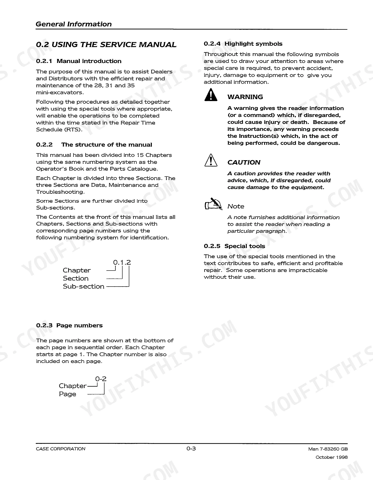
| General Information | 21-40 | Safety Precautions, Using the Service Manual (Manual Introduction, Structure of the Manual, Page Numbers, Highlight Symbols, Special Tools) |
| Engine | 41-50 | Engine Data, Engine Maintenance, Main Hydraulic Pump Drive Coupling, Engine Troubleshooting |
| Cooling System | 51-60 | Radiator Cap, Thermostat, Cooling Fan, Radiator, Oil Cooler |
| Fuel, Air and Exhaust | 61-74 | Fuel, Air, Exhaust, Fuel Tank, Air Filter, Exhaust System, Fuel Lift Pump, Agglomerator |
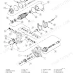
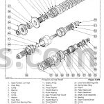
| Track Gearbox | 75-108 | Hydraulic Motor, Control Valve, Cylinder Block, Piston, Valve Plate, Output Shaft, Swash Plate |
| Brakes | 109-110 | Track Drive, Slew Drive |
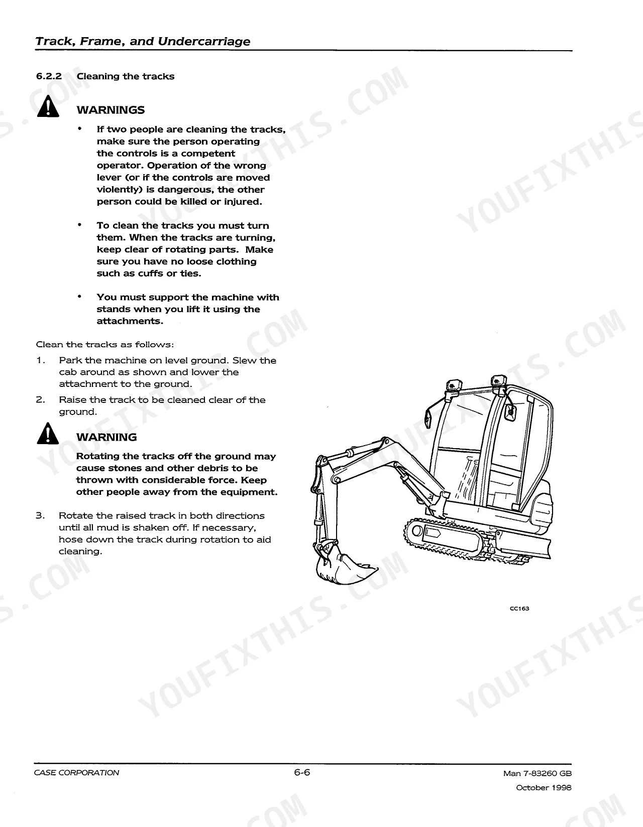
| Track, Frame, and Undercarriage | 111-134 | Track, Frame, Undercarriage, Rubber Track, Metal Track, Lower Roller, Drive Sprocket, Idler |
| Cab and ROPS | 135-138 | Cab, ROPS, Cab Glazing, Wiring Harness, Lifting Eyes, Mounting Bolts, Rubber Mounts, Spacers |
| Sheet Metal and Covers | 139-160 | External Covers, Internal Covers, Engine Cover, Bumpers, Bulkhead, Counterweight, Sump Guard, Seat |
| - |
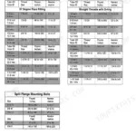
Quick Reference Specifications
| Specification | Value | Page |
|---|---|---|
| Lower roller Overall O/D nominal | 118 mm | p. 113 |
| Lower roller Overall O/D tolerance | -6 mm | p. 113 |
| Battery Voltage | 12V | p. 32 |
| Starter Motor Power | 2 kW | p. 32 |
Case 28, 31, 35 Common Problems This Manual Covers
Pins and bushings in bucket linkage or undercarriage seized or worn prematurely
Remove the linkage pins and inspect the bushing bore and pin shank for galling or scoring. Grease every fitting until fresh grease purges from both sides of each joint — one to three shots per point on a daily interval. Refer to the boom, dipper, and linkage section starting on page 263 for pin location diagrams. After reassembly, cycle the attachment through full range three times to confirm free movement with no binding.
Manual Section: Boom, Dipper, and Linkage p. 263Engine won't crank or turns over slowly, battery voltage reading low
Measure battery voltage at the terminals — spec is 12V negative earth. If reading is below 12V under load, check battery specific gravity and inspect the alternator charging output. Verify the starter motor draws no more than the rated 2 kW; excessive draw points to worn brushes or a seized pinion. Follow the electrical troubleshooting sequence on pages 173-174 to isolate whether the fault is in the battery, alternator, or starter circuit before pulling components.
Manual Section: Electrical System p. 173Slew motor turns sluggishly, slewing is unstable, or oil leaks from slew joint
Check the superstructure troubleshooting chart on page 318 to confirm whether the fault is in the relief valve, parking brake, or reduction gear. Inspect the swivel joint for external leaks at the joint circumference — any weeping here contaminates the entire slew circuit. Test slow-speed slewing control separately from full-speed rotation; if only slow speed fails, the solenoid valve is the likely culprit. Cross-reference hydraulic system troubleshooting on for solenoid valve fault isolation steps.
Manual Section: Superstructure (Including Slew Motor) p. 318Frequently Asked Questions
What are the recommended service intervals?
The manual provides a maintenance schedule with recommended service intervals. These include daily checks (10 hours), and checks every 50 hours, 250 hours, 500 hours, and 1000 hours. Each interval lists specific items to inspect or service. p. 16
How do you fix final drive grinding noise or oil leaking from track gearbox motor?
Check the track gearbox oil level before anything else. Drain and inspect for metal particles — contaminated oil confirms internal wear. Verify all joint seals are intact; replace any that show weeping. Consult the troubleshooting index on pages 107-107 for fault isolation. Refill with the manufacturer-specified gear oil and confirm no leaks persist after a 15-minute test run. p. 107
How do you fix hydraulic system overheating, pressure low, or fluid leaking from cylinders or hoses?
Inspect all hydraulic hose connections and cylinder rod seals for weeping or active leaks. Check the piston rod sliding surface and rod cover outer circumference for seal integrity per the cylinder troubleshooting guide on pages 285-286. Verify system pressure meets the spec listed on page 175. If a cylinder shows natural fall beyond acceptable limits, remove the rod cover and inspect the piston seal pack before reassembly. p. 285
How do you fix tracks wearing sprocket unevenly or machine pulls to one side while traveling?
Inspect track tension and alignment per the undercarriage troubleshooting chart on page 133. Check lower roller tread area diameter — nominal is 118 mm, replace if worn beyond -6 mm tolerance. Verify idler flange thickness is within 40 mm nominal; swap idler if below -4 mm limit. Measure upper roller tread and replace if past -6 mm tolerance on the tread diameter (per page 114 specs). p. 133
What format is this manual in?
This is a 324-page searchable PDF ready for immediate download. Works on any device, so pull it up on your phone while you're under the hood. No shipping, no waiting.
Is this Service Manual printable?
The PDF is DRM-free. Print whatever sections you need to take out to the shop. Standard letter or A4 paper works.
Does this Service Manual have electrical diagrams?
Included. The Service Manual covers complete wiring harness diagrams, electrical circuits, and connector pinouts.


Reviews
There are no reviews yet.