


Part of the Case Repair Manuals.
This 759-page Case 821C Loader, 721C Loader Service Manual (OEM #7-13451) puts the complete factory rebuild process for both wheel loaders in one searchable file. Inside you get full electrical troubleshooting with wiring schematics, hydraulic system diagrams covering the loader control valve and cylinders, and torque tables for decimal, metric, and steel hydraulic fittings. You also pull up power train, steering, and brake procedures with the same pressure-check and troubleshooting depth your dealer uses. Set hydraulic hose fittings (1/4-inch tube OD, 7/16-20 thread) to 72 to 144 pound-inches, and confirm the system holds 174 litres before you chase a phantom leak. No more guessing why the loader control valve won't hold pressure. Bookmarked by section so you jump straight from Power Train to Hydraulics without scrolling, then pull it up on your phone right at the machine and get back to work.
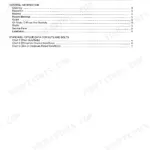
What's Inside This Case 821C, 721C Manual
| System | Pages | Key Topics |
|---|---|---|
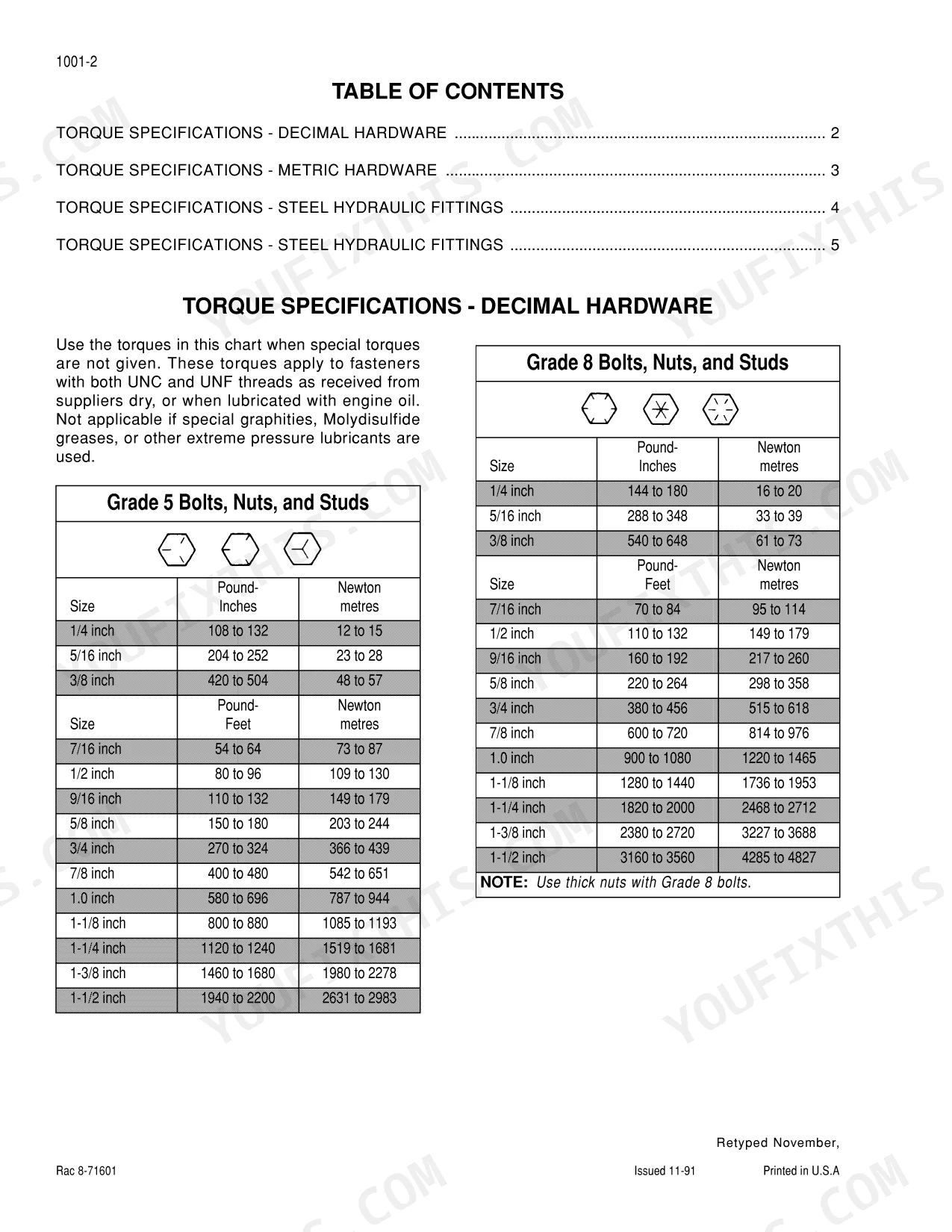
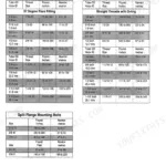
| General | 5-18 | Standard Torque Specifications (Decimal Hardware, Metric Hardware, Steel Hydraulic Fittings) |
| Engine | 19-40 | Engine and Radiator Removal and Installation, Stall Test |
| Fuel System | 41-42 | - |
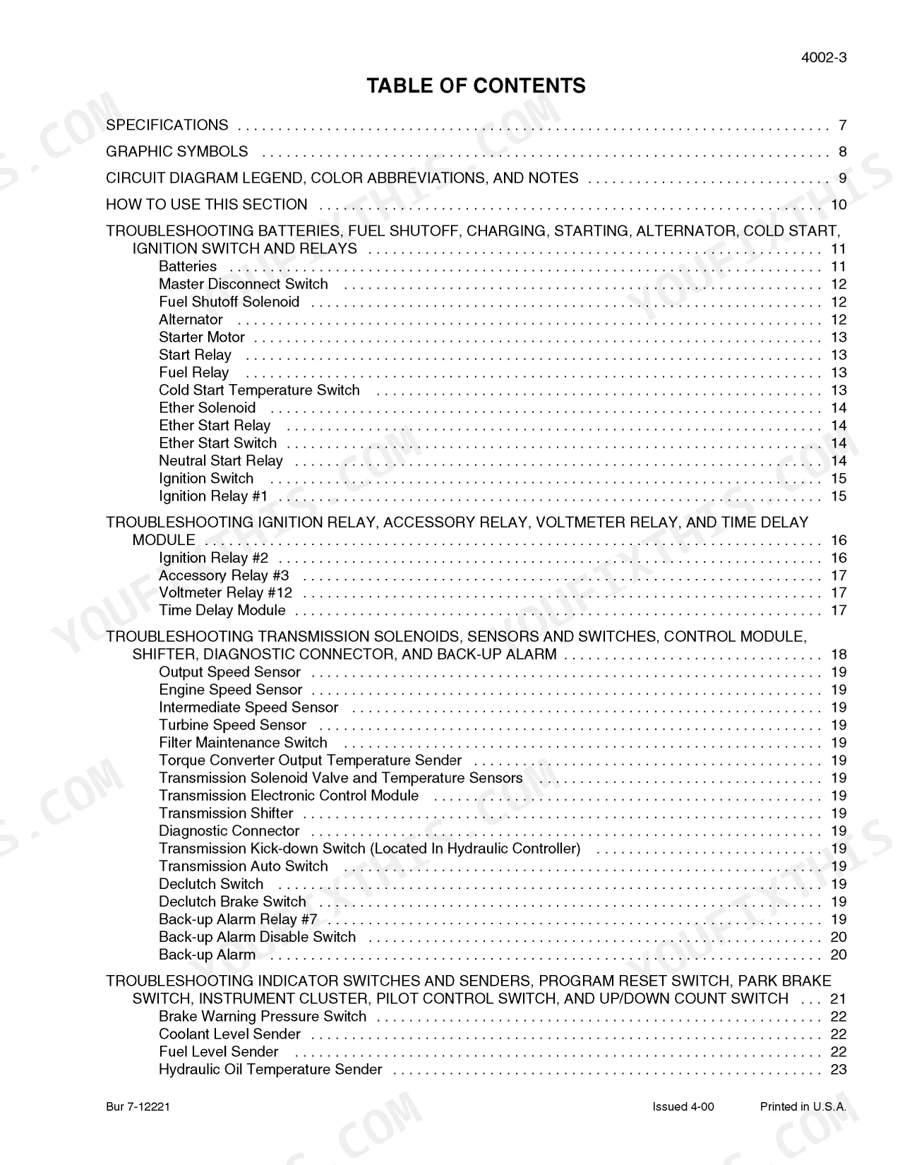
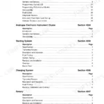
| Electrical | 43-217 | Removal and Installation of Starter and Alternator, Electrical Specifications, Troubleshooting, And Schematics, Batteries, Starter and Starter Solenoid |
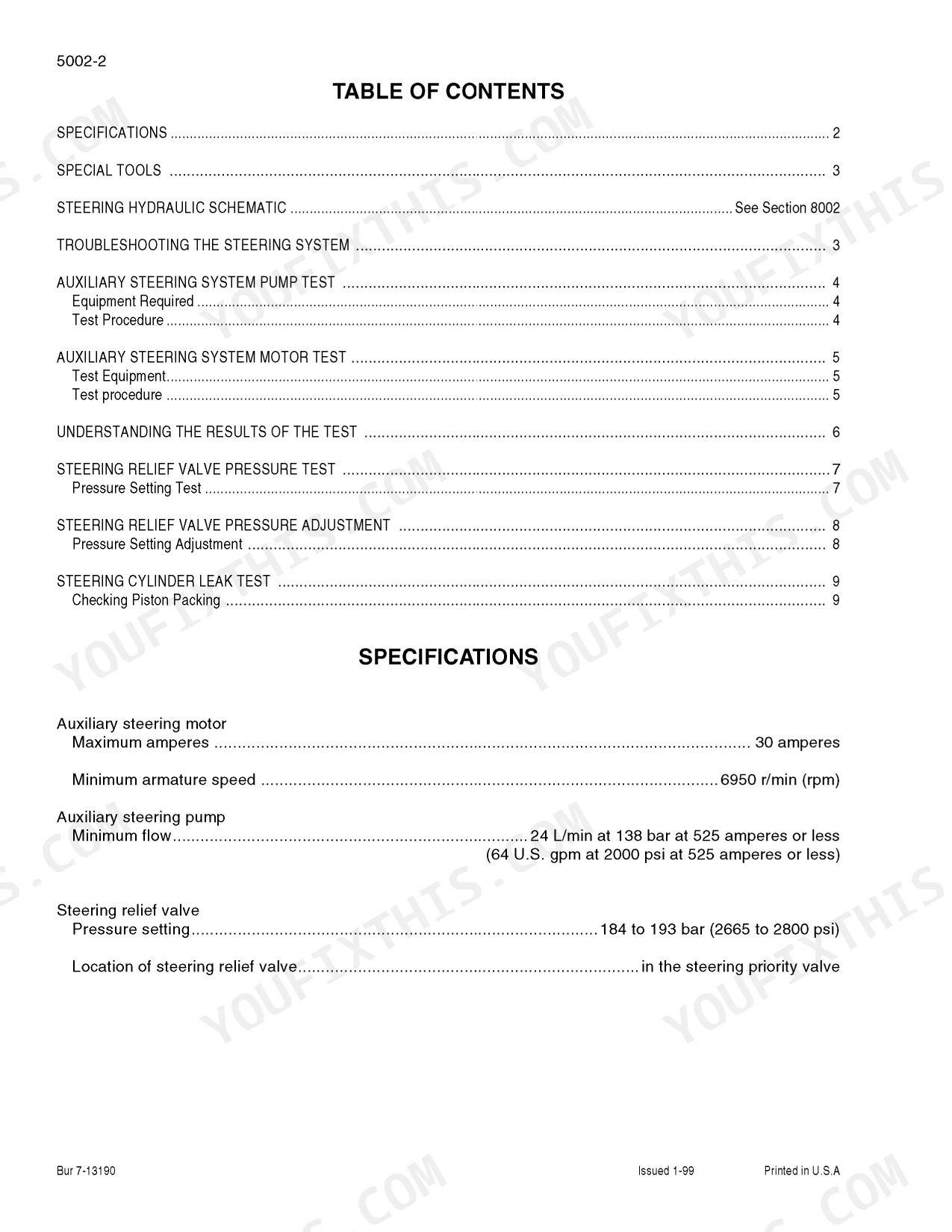
| Steering | 218-269 | Removal and Installation of Steering Components, Steering Specifications, Pressure Checks, And Troubleshooting, Steering Control Valve |
| Power Train | 270-434 | Transmission Specifications, Pressure Checks, And Troubleshooting, Transmission, 821C Front Axle, 721C Front Axle - 821C Rear Axle, Drive Shaft |
| Brakes | 435-476 | Removal and Installation of Brake Components, Hydraulic Brake Troubleshooting, Brake Accumulators, Brake Actuator Valve, Brake Accumulator Valve |
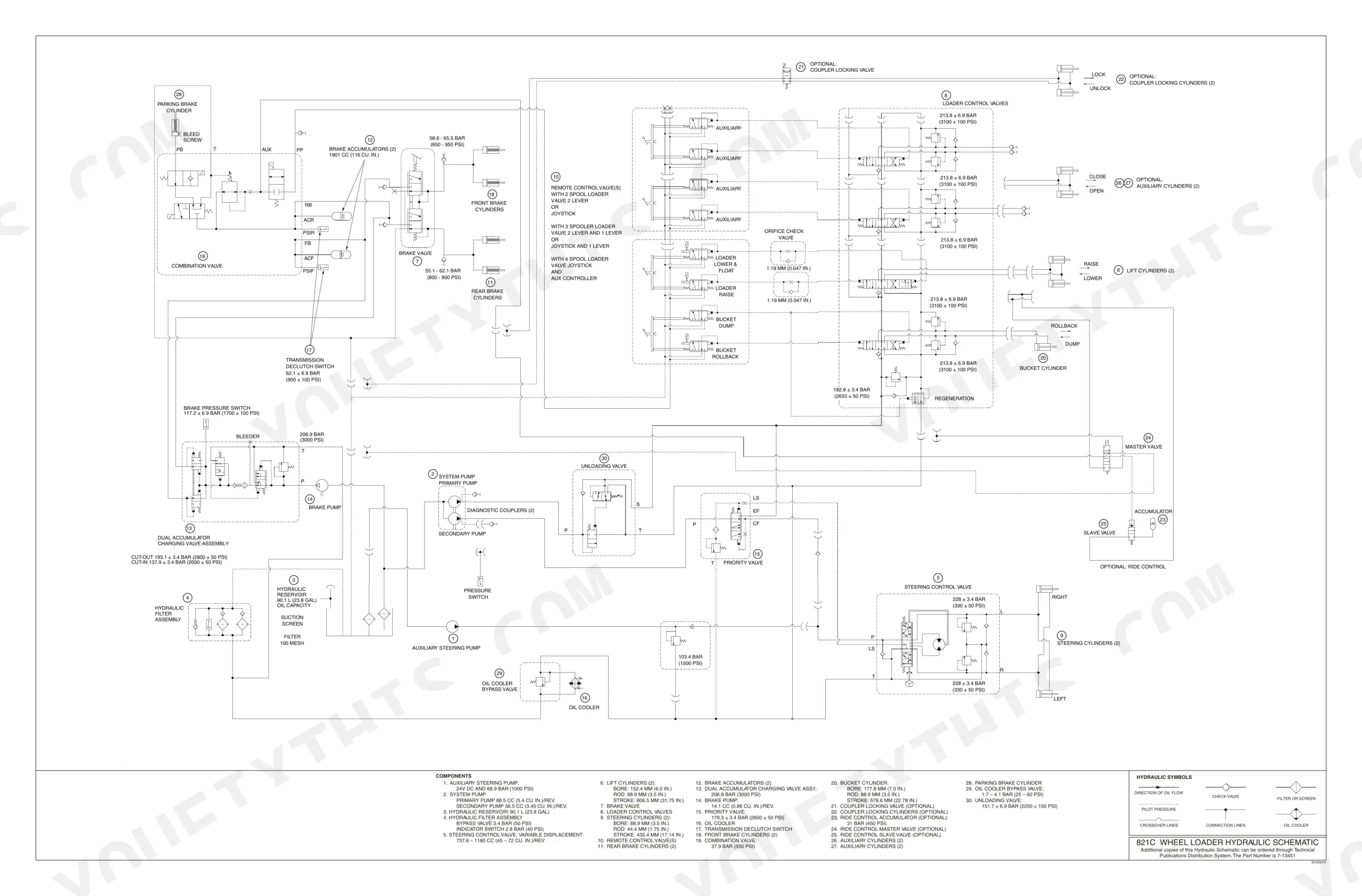
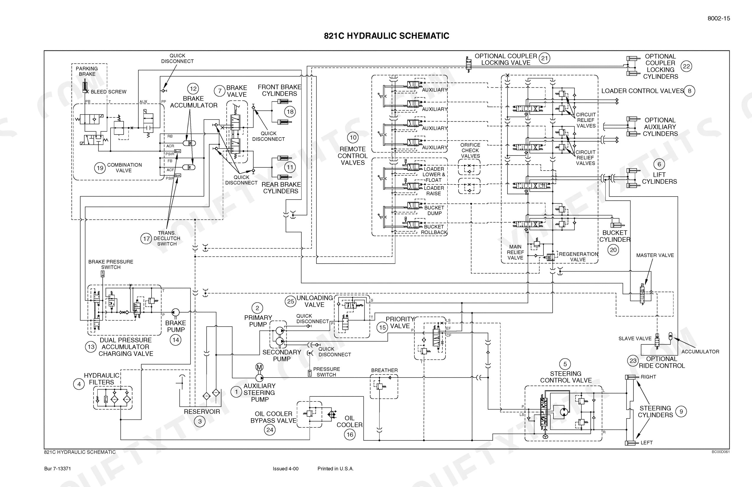
| Hydraulics | 477-651 | Removal and Installation of Hydraulic Components, Hydraulic Specifications, Troubleshooting, And Pressure Checks, Cleaning the Hydraulic System |
| Mounted Equipment | 652-756 | Pedals and Levers, Air Conditioning Troubleshooting and System Checks for Systems with HFC-134a Refrigerant, Air Conditioner System Service |
| Hydraulic and Electrical Schematics | 757-759 | Wiring Diagrams, Hydraulic Circuit Diagrams, Schematic Sheets, Connector Pinouts |
Quick Reference Specifications
| Specification | Value | Page |
|---|---|---|
| All Models | ||
| Hydraulic hose fitting torque (1/4 inch tube OD, 7/16-20 thread) | 72 to 144 pound-inches (8 to 16 Newton metres) | p. 10 |
| Accumulator charge valve cut out pressure | 187 to 194 bar (2715 to 2815 psi) | p. 449 |
| Normal operating oil temperature (above ambient) | 56 degrees C (100 degrees F) | p. 290 |
| Total hydraulic system capacity | 174 litres | p. 14 |
| Transmission oil operating temperature | 80 to 120 °C | p. 274 |
| Accumulator nitrogen charge pressure | 55 to 57 bar | p. 447 |
| Steering relief valve pressure setting | 184 to 193 bar | p. 231 |
| Cab and canopy mounting bolts torque | 786 to 840 Nm | p. 743 |
| Parking brake adjustment (M16 adjusting screw) | 0.5 to 1.5 mm | p. 656 |
| 821C Loader | ||
| In-line fuel filter replacement | USE CASE FILTERS | p. 17 |
| 621C/921C | ||
| Brake pump output | 27.4 L/min at 172 bar | p. 447 |
| 721C/821C | ||
| Brake pump output | 32 L/min at 172 bar | p. 447 |
Case 821C, 721C Common Problems This Manual Covers
Case 821C/721C hydraulic hose fittings leak at connections, bucket and loader arm respond sluggishly
Inspect all hydraulic hose fittings for cracking, weeping, or improper torque. Tighten 1/4 inch tube fittings to 72 to 144 pound-inches (8 to 16 Newton metres) per the torque chart on page 10. Replace any hose showing cover abrasion or swelling rather than re-tightening a worn fitting.
Manual Section: General p. 10Engine won't start or stalls immediately after performing routine oil and fluid maintenance checks
Drain and inspect the fuel and oil sampled during the last service for contamination before restarting. Bleed air from the fuel lines at the filter housing. On the 821C, replace the in-line fuel filter with Case filters only, as specified on page 17. Verify oil level on the dipstick before cranking the starter.
Manual Section: General p. 17Machine runs hot and overheats during heavy loader work in warm weather
Check the cooling system for debris blocking the radiator and hydraulic oil cooler fins; clean with low-pressure air or water. Verify oil temperature at the test point; normal operating temperature runs about 56 degrees C (100 degrees F) above ambient per page 290. If readings exceed that, inspect the fan drive and thermostat.
Manual Section: Power Train p. 290Transmission overheats with oil temperature climbing well above normal operating range during heavy hauling
Check transmission fluid level and condition first; low or degraded oil reduces cooling capacity under load. Normal transmission oil operating temperature runs 80 to 120 °C (176 to 248 °F) per the specifications on page 274. If temperature exceeds this range, inspect the transmission oil cooler for blockage and verify the cooling fan operates correctly.
Manual Section: Power Train p. 274Steering feels heavy or unresponsive with reduced turning effort at low engine RPM
Start the engine and bring it to operating RPM before testing; low idle reduces pump output and feels like a steering fault. Check the steering relief valve pressure setting on page 231; it should read 184 to 193 bar (2665 to 2800 psi). A reading below spec points to a worn relief valve or steering pump.
Manual Section: Steering p. 231Brake pedal feels spongy or loses pressure intermittently during heavy loader operation on grade
Bleed the brake hydraulic circuit at each wheel cylinder to remove trapped air before condemning the accumulator. Check the accumulator charge valve cut out pressure; it should read 187 to 194 bar (2715 to 2815 psi) per the specifications on page 449. A low cut-out reading means the accumulator needs recharging or the valve needs replacement.
Manual Section: Brakes p. 449Frequently Asked Questions
How quickly can I access this Case 821C Loader, 721C Loader manual after buying?
Instant PDF download (140 MB). You get the full 759-page searchable Service Manual immediately after payment. Open it on your laptop, tablet, or phone right in the shop.
Can I print specific sections of this Case 821C Loader, 721C Loader manual?
Zero restrictions. The PDF is DRM-free. Print whatever sections you need to take out to the shop. Standard letter or A4 paper works.
Does this Case 821C Loader, 721C Loader Service Manual have electrical diagrams?
Yes. You'll find full electrical schematics with wire routing diagrams, connector identification, and circuit descriptions.


Reviews
There are no reviews yet.