


Part of the Case Repair Manuals.
All 580 pages of this Case 3388, 3588, 3788, 6388, 6588, 6788 service manual pdf (OEM #GSS-1490-2) focus on keeping your Case tractors pulling hard in the field. Inside, you get full electrical wiring diagrams, complete power priority hydraulic schematics, and extensive troubleshooting charts for the Power Flow gear drive. We packed this reference with step-by-step teardown procedures for the independent power take-off (IPTO), torque amplifier overhauls, and multiple control valve diagnostics. Verify your orifice screen opening is exactly .508 mm and tighten the torque amplifier solenoid to 10.8-13.6 N-m before running pump standby pressure tests. You cannot afford to guess on hydraulic flow rates during a breakdown. Grab this bookmarked digital download, pull it up on your shop tablet, and fix the machine right the first time.
What's Inside This Case 3388–6788 Series Manual
| System | Pages | Key Topics |
|---|---|---|
| Safe Work Rules | 6-7 | Hydraulic Jacks, Hoists, Frame Lock Pin, Safety Stands, Hydraulic Cylinders, Electrical Storage Batteries, Fuel Tank, Tubeless Tires |
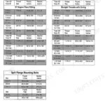
| Standard Torque Data for Nuts and Bolts | 8-9 | Type 1 Bolts, Type 5 Bolts, Type 8 Bolts, Class 5.8 Bolts, Class 8.8 Bolts, Class 10.9 Bolts |
| Metric Conversion Tables | 10-11 | - |
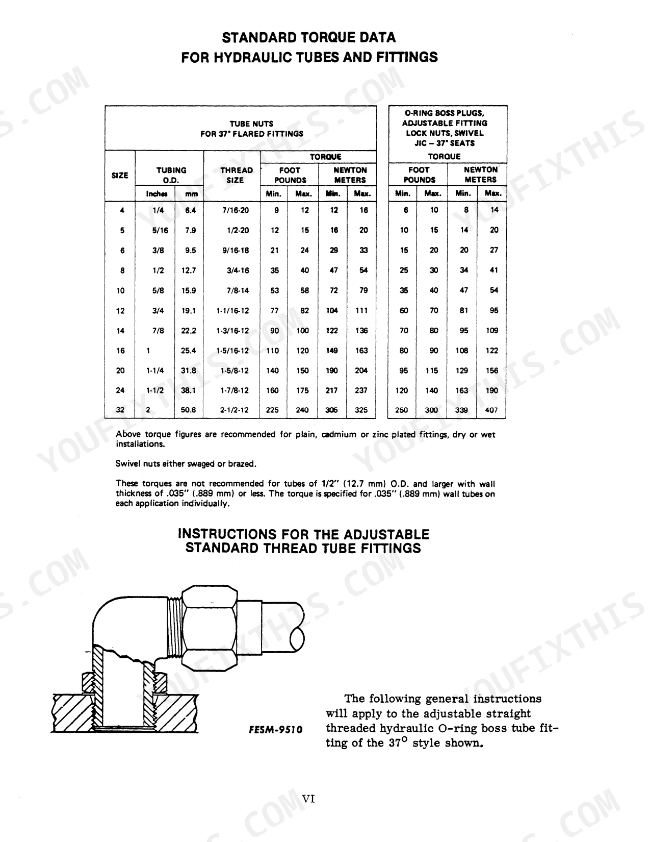
| Standard Torque Data for Hydraulic Tubes and Fittings | 12-13 | Tube Nuts, O-Ring Boss Plugs, Adapters, Swivel Lock Nuts, Swivel Jic - 37° Seats |
| Flangette Bearing Installation | 14 | Metric Nuts, Bolts |
| Special Service Tools Required | 15-19 | Lifting Brackets, Puller, Engine Stand, Hydraulic Hand Pump Test Kit, Splitting Adapter Brace, Pfc Hydraulic System Analyzer Kit |
| Service Information System (S.I.S.) | 20-22 | Pfc Hydraulic System, Data Centers, Electrical System, Air Induction System, Ambac Injection Pumps, Robert Bosch Rotary Injection Pumps, Axial Flow Combines, Cyclo Planter |
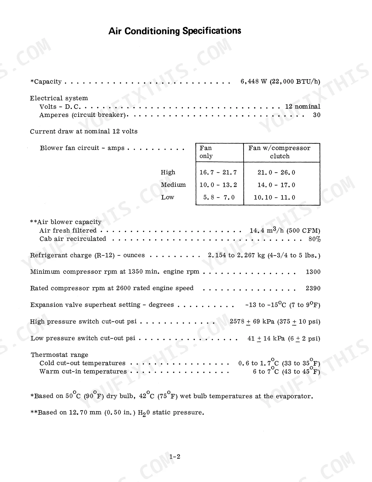
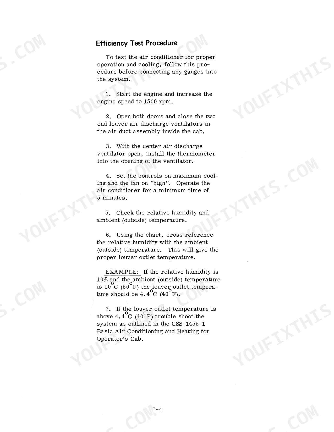
| A/C and Tractor Splits | 23-110 | Air Conditioning Specifications, Air Conditioning Components, Windshield Wiper Motor, Door Striker Adjustment, Recirculation Rod and Door, Transfer Case, Transmission, Rear Split |
| Front Axle Assembly | 111-140 | Front Axle Removal, Axle Carrier, Axle Differential and Pinion, Pinion, Differential, Planetary Assembly |
| Steering | 141-164 | Steering Cylinder, Cylinder Bushings, Steering Hand Pump |
| Engine | 165-170 | Oil Cooler, A/C Condenser, A/C Compressor, Throttle Cable, Main Electrical Harness, Fuel Supply, Fuel Return |
| Fuel System and Hoods | 171-184 | Main Fuel Tank, Auxiliary Fuel System, Auxiliary Fuel Tank, Front Hood, Rear Hood Adjustment |
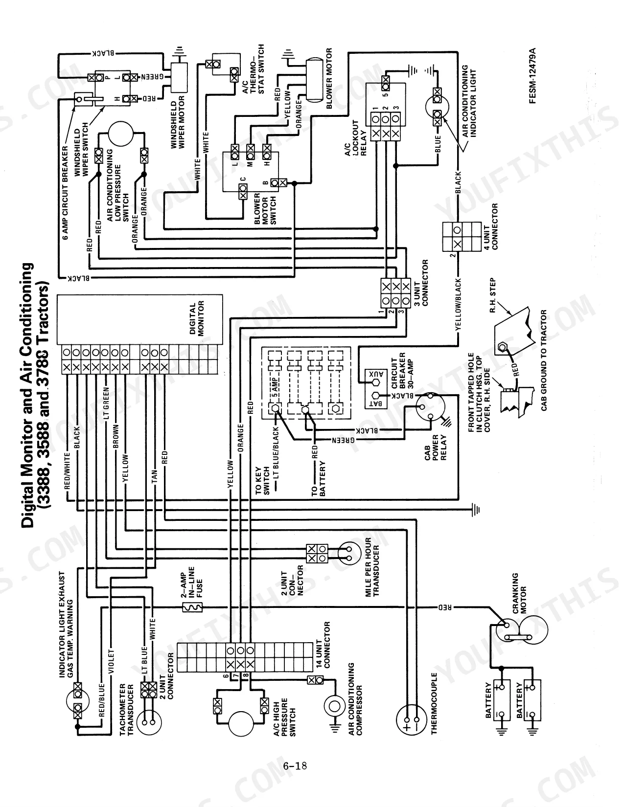
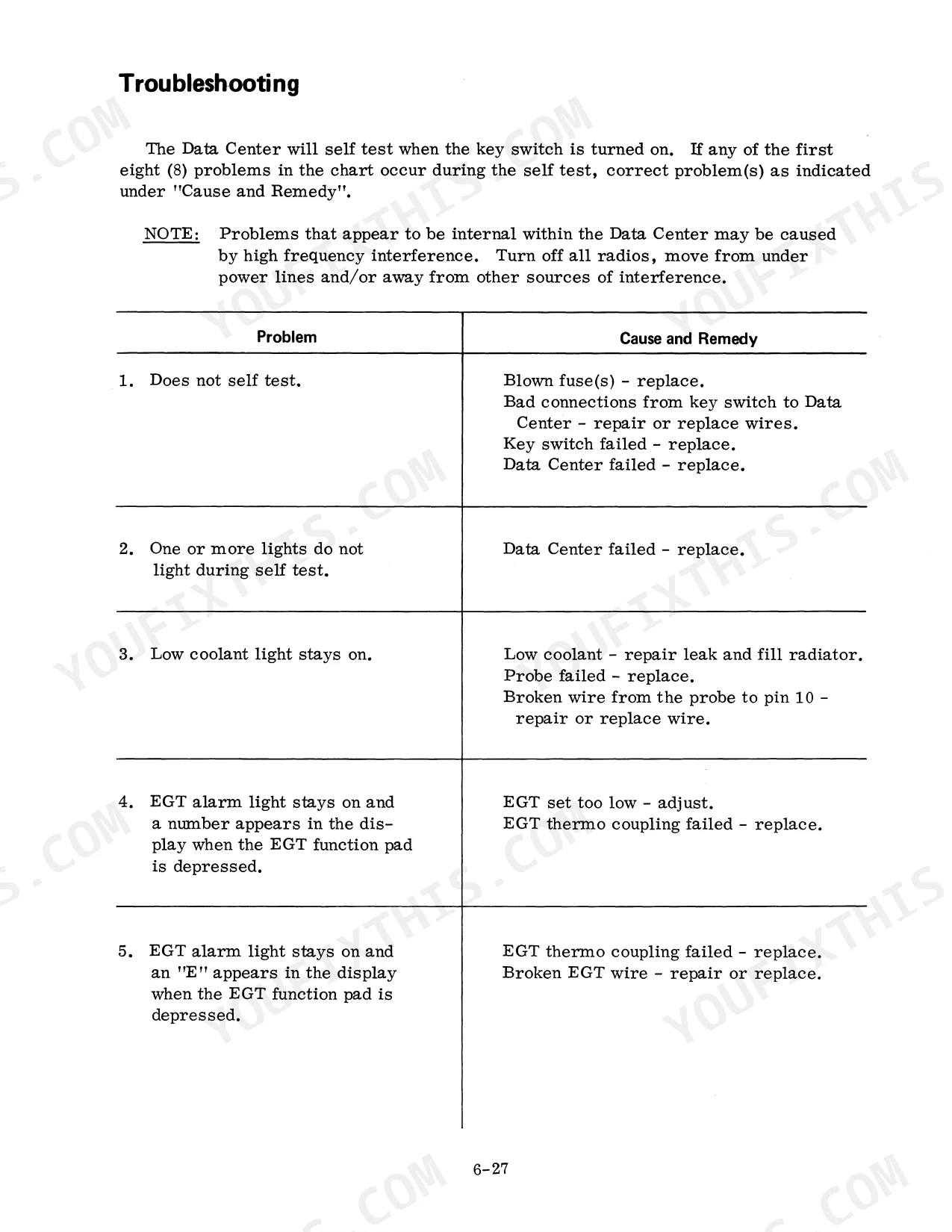
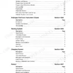
| Electrical System | 185-224 | Specifications, Digital Data Center, Instrument Gauge, Transducer, Wiring Diagrams, Troubleshooting |
| Cooling System | 225-226 | Radiator, Air Intake, Radiator Wire, Radiator Capscrews |
| Clutch and Flywheel | 227-242 | Clutch Specifications, Clutch Assembly, Clutch Linkage Adjustment, Clutch Booster, Ta Spool Adjustment, Park Lock and Neutral Starting Switch |
| Transmission and Transfer Case | 243-338 | Transfer Case, Flywheel Shaft Adjustment, Power Flow Gear Drive, Speed Transmission Disassembly, Torque Amplifier Overhaul, Ipto Drive Shaft |
| Rear Differential | 339-370 | Pinion and Differential Adjustment, Differential Lock, Rear Frame Cover Service, Draft Control Cylinder, Rockshaft, Torsion Bar and Crankarm Shaft Bushings |
| Rear Axle Housing and Wheels | 371-382 | Rear Drive Axle Assembly, Rear Axle and Bull Pinion Shaft, Removal, Disassembly, Reassembly and Installation, Rear Axle Bearings Preload Adjustment |
| Brakes | 383-396 | Power Hydraulic Multi-Disc Brakes, Power Brake Valve, Brake Pedal and Linkage Adjustment, Brake Wear Switch Adjustment, Bleeding the Brakes |
| Independent Power Take-Off | 397-430 | Ipto Assembly Drawings, Ipto Introduction, Removing the Ipto From the Tractor, Servicing Ipto Components, Ipto Control Valve, Adjusting Ipto Pressure |
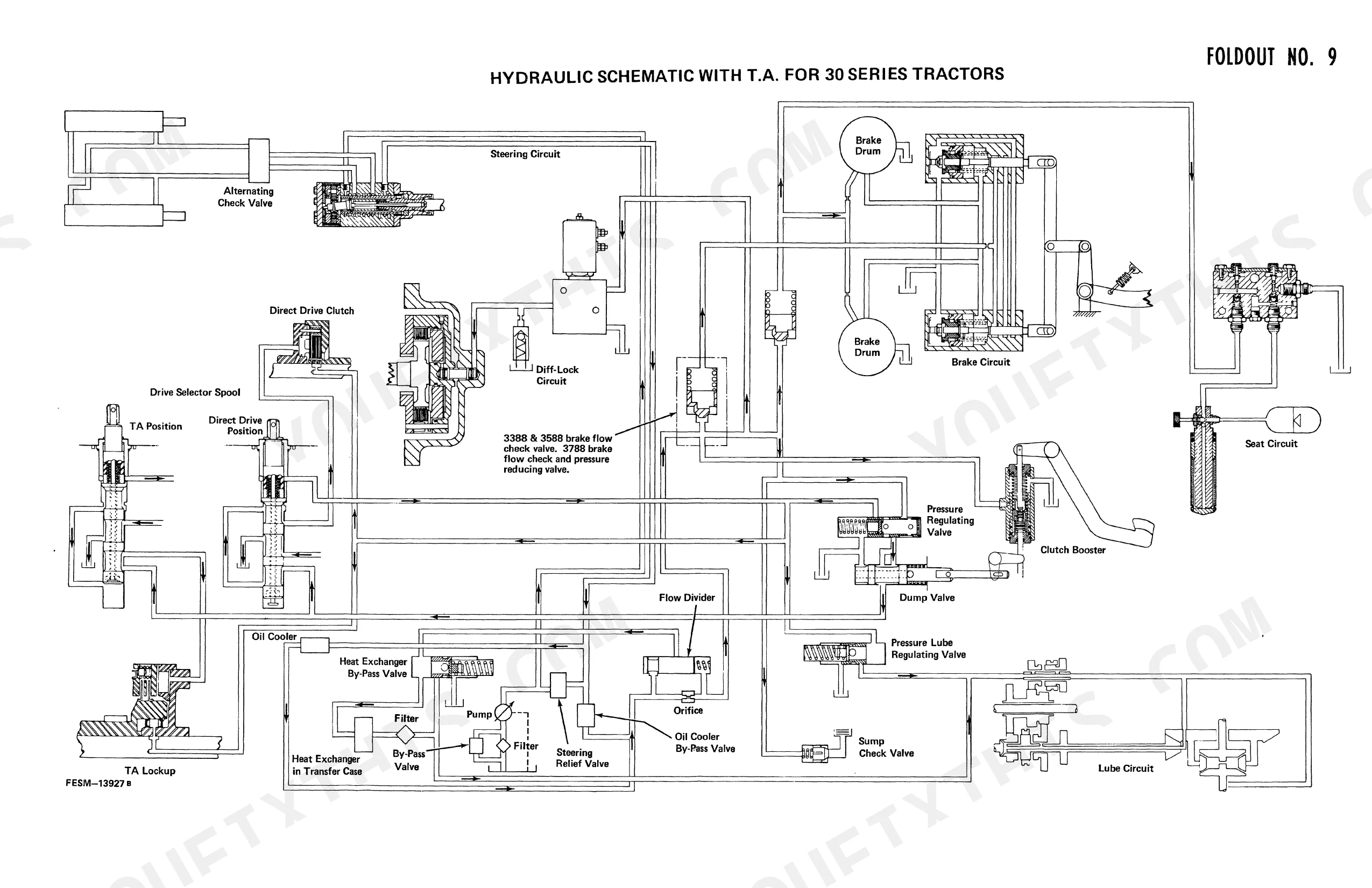
| Hydraulic System | 431-520 | Basic Hydraulic System, Operation of Power Priority Hydraulics, Multiple Control Valve (Mcv), Hydraulic Steering Pump, Hydraulic Hitch Pump and Compensator, Auxiliary Valve Service |
| Testing Hydraulic System | 521-580 | Specifications, Hydraulic System Analyzer (14-557) Installation, Pump Flow Rate and Cut-Off Pressure, Pump Standby Pressure, Pump Differential Pressure, Troubleshooting Charts |
Quick Reference Specifications
| Specification | Value | Page |
|---|---|---|
| All Models | ||
| Filter micron rating | 25 micron | p. 441 |
| Orifice screen opening | .508 mm (.020 in.) | p. 527 |
| Orifice screen torque | 9 to 10 N·m (7 to 8 ft. lbs.) | p. 527 |
| Steering Cylinder Rod Nut Torque | 664 to 725 N·m (489 to 534 ft. lbs.) | p. 144 |
| 6388, 6588 and 6788 Tractors | ||
| Torque amplifier solenoid torque | 10.8 to 13.6 N·m (8 to 10 ft. lbs.) | p. 255 |
| IPTO cable length (engaged) | 75.5 mm (3 inch) | p. 425 |
| 3388 S/N 10999 and Below | ||
| PTO Pressure | 1585 to 1654 kPa (230 to 240 psi) | p. 397 |
| 3588, 3788, 6388, 6588 and 6788 Tractors | ||
| PTO Pressure | 1413 to 1482 kPa (205 to 215 psi) | p. 397 |
Case 3388–6788 Series Common Problems This Manual Covers
Torque amplifier solenoid shifts erratically or won't engage on 6388, 6588 and 6788 models
Pull the solenoid and check it for sticking or a weak coil. On reinstall, torque the mounting to 10.8 to 13.6 N·m (8 to 10 ft. lbs.) as specified on page 255. Confirm 12V is reaching the solenoid at the connector before replacing it; a loose mount or under-torqued fastener will mimic a bad coil.
Manual Section: Transmission and Transfer Case p. 255IPTO cable slips out of adjustment, engagement lags or won't fully disengage on 6388, 6588 and 6788 models
Check the IPTO cable adjustment on page 425. With the lever engaged, the cable should measure 75.5 mm (3 inch) at the adjustment point. Loosen the jam nut, reset the length to spec, and retighten. Cycle the lever fully and confirm clean engagement and disengagement before road testing.
Manual Section: Independent Power Take-Off p. 425Frequently Asked Questions
How to adjust auxiliary valve unlatching pressure on International Harvester 3788/6788?
To adjust the auxiliary valve unlatching pressure during "Test No. 8 Auxiliary Valve Unlatching Pressure" for 3788 & 6788 tractors, use a screwdriver to turn the adjusting screw 1/4 turn and recheck the pressure. Repeat this procedure until the specified unlatching pressure of 13,789 to 16,880 kPa (2000 to 2450 psi) is obtained. p. 538
How do you fix international harvester 6788 hydraulic flow and pressure low in one direction but normal in reverse?
Run the comprehensive hydraulic tests starting on page 521. Hook up the analyzer at the motor circuit and watch both directions separately. If reverse reads fine but forward stays weak, pull the motor check valve and inspect the seat for scoring or debris; a valve that won't seat fully bleeds pressure on only one side. p. 521
How do you fix no hydraulic flow in either direction at the pump?
Check the hydraulic oil filter first; it's a 25 micron element on the right side of the rear frame, on page 441. If flow is still dead, pull the orifice screens from the pump flange and confirm the .508 mm (.020 in.) orifice on page 527 isn't plugged. Clean it, reinstall, and retorque the screen to 9 to 10 N·m (7 to 8 ft. lbs.). p. 441
How do you fix low flow at auxiliary valves while flow reads correct at the motor valve?
Follow the auxiliary circuit test sequence on page 521 with the analyzer tee'd in ahead of the aux bank. A correct reading at the motor valve with weak flow downstream usually points to the motor check valve not seating; remove it, check the sealing face for wear, and verify the 25 micron filter on page 441 isn't restricting supply before condemning the pump. p. 521


Reviews
There are no reviews yet.