


Part of the Case Repair Manuals.
Looking for the official factory specs for your Case Skid Steer Compact Track Loader? This 526-page Case 410, 420 service manual PDF (OEM #87364090 NA) breaks down every hydrostatic pump, drive motor, and electrical system for the 410, 420, and 420CT models. You get full electrical schematics to trace stubborn voltage drops, complete hydraulic routing for the gear pumps and cylinders, and step-by-step hydrostatic system troubleshooting charts. Open to any section and find detailed teardown procedures for the drive sprockets, idler wheels, and piston pumps, along with complete fluid capacity tables. Verify your starter armature runout stays under 0.05 mm (0.002 inch) and dial in the 410 brake system release pressure between 160 and 217 psi before rolling out of the bay. Stop hunting down random forum advice when a machine is stranded. Download this bookmarked file right to your tablet, pull up the exact schematic you need, and get the loader back in the dirt.
What's Inside This Case 410, 420, 420CT Manual
| System | Pages | Key Topics |
|---|---|---|
| General | 9-30 | Section Index - General, Fluids and Lubricants (Capacities and Lubricants, Environment, Engine Lubrication, Diesel Fuel System), Standard Torque Specifications |
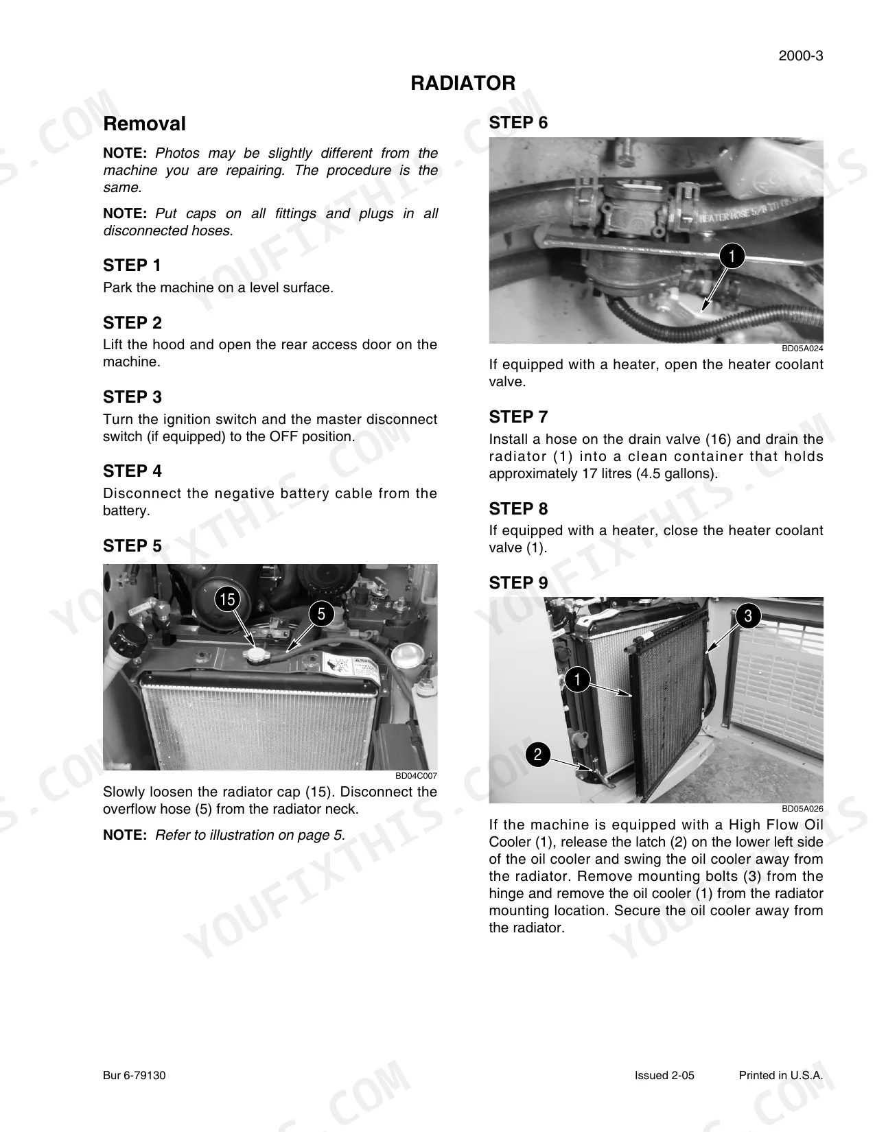
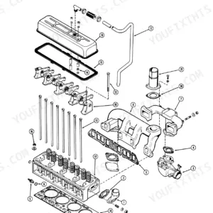
| Engine | 31-52 | Section Index - Engines, Engine and Radiator Removal and Installation, For Engine Repair - See Engine Service Manual |
| Fuel System | 53-56 | Section Index - Fuel Systems, For Fuel System Repair - See the Engine Service Manual |
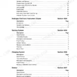
| Electrical System | 57-192 | Section Index - Electrical, Electrical Specifications and Troubleshooting and Schematics, Battery, Starter and Starter Solenoid |
| Tracks | 193-216 | Rubber Track, Track Tensioning Mechanism, Drive Sprocket, Front Idler Wheel, Rear Idler Wheel, Rollers |
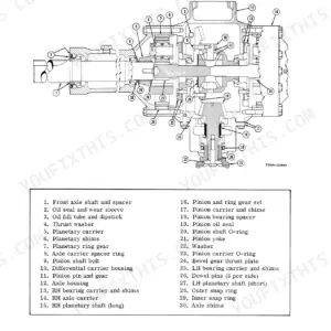
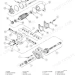
| Power Train | 217-330 | Section Index - Power Train, Hydrostatic System Troubleshooting, Removal and Installation of Hydrostatic Components, Drive Coupling, Piston Pump, Drive Motors |
| Brakes | 331-358 | Section Index - Brakes, Removal and Installation of Park Brake Components, Brakes - Spring Applied - Hydraulic Release |
| Hydraulics | 359-464 | Hydraulic System Troubleshooting, Hydraulic Components, Gear Pump, Cylinders, Flat Faced Couplers, Accumulator for Ride Control |
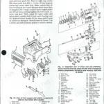
| Mounted Equipment | 465-524 | Pedals and Levers, Loader, Attachment Coupler, ROPS Canopy, Heater |
| Schematic Set | 525-526 | - |
Quick Reference Specifications
| Specification | Value | Page |
|---|---|---|
| All Models | ||
| Brush length (less than) | 11 mm (7/16 inch) | p. 181 |
| Armature runout (not more than) | 0.05 mm (0.002 inch) | p. 182 |
| Auxiliary hydraulics foot pedal position | Make sure the auxiliary spool in the control valve is in the neutral position. Adjust the cable until the auxiliary hydraulic pedal is in the horizontal position. | p. 479 |
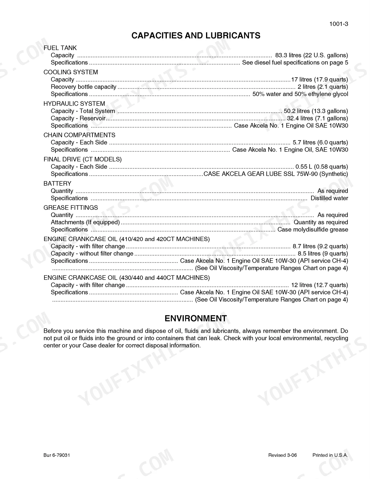
| Fuel Tank Capacity | 83.3 litres | p. 13 |
| Hydraulic System Total System Capacity | 50.2 litres | p. 13 |
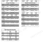
| Wheel Nuts (Solid Center Wheels) | 224 to 265 Nm | p. 311 |
| 410 | ||
| 410 Brake System Release Pressure - Maximum - Fully Disengaged | 1100 to 1500 kPa (11 to 15 bar) (160 to 217 psi) | p. 335 |
| 410 Hydraulic Drive Motor Mounting Bolts | 56 Nm plus Turn Additional 65° | p. 231 |
| 420 | ||
| 420 Brake System Release Pressure - Maximum - Fully Disengaged | 2760 kPa (27.6 bar) (400 psi) | p. 335 |
| 420 Hydraulic Drive Motor Mounting Bolts | 122 Nm plus Turn Additional 60° | p. 231 |
| 410, 420, 420CT | ||
| Engine Crankcase Capacity | 8.7 litres | p. 13 |
| 420CT | ||
| 420CT Final Drive Motor Mounting Bolts Initial Torque | 67 to 163 Nm | p. 231 |
Case 410, 420, 420CT Common Problems This Manual Covers
Case 420 engine fails to start when cold below 40 degrees even with glow plugs engaged
Remove the starter motor and inspect the brush length as detailed on page 181. Replace the brush holder assembly if the brush fastened to it measures less than 11 mm (7/16 inch). Verify armature runout does not exceed 0.05 mm (0.002 inch) on page 182.
Manual Section: Starter and Starter Solenoid Test Procedures p. 181Parking brake engages and does not unlock or release when commanded by the operator
Test the brake system release pressure. For 410 machines, verify the maximum pressure when fully disengaged reaches 1100 to 1500 kPa (160 to 217 psi) as shown on page 335. If pressure falls short, inspect the solenoid and apply 11 120 N (2500 pound-force) friction stack compression force on page 354.
Manual Section: Brakes p. 335Engine will not turn over because the auxiliary hydraulics foot pedal is stuck out of neutral
Inspect the auxiliary spool in the control valve and confirm it rests in the neutral position. Adjust the control cable until the auxiliary hydraulic pedal sits completely horizontal as described on page 479. Start the machine and verify low idle engine speed stays at 1050 ± 50 r/min.
Manual Section: Mounted Equipment p. 479Reduced loader lifting capacity and slow boom movement during heavy material handling
Check the loader control valve main relief pressure on page 363. Connect your test gauge and verify the system maintains 20 700 ± 345 kPa. If pressure drops below specification, inspect the gear pump flow and verify total hydraulic system capacity holds exactly 50.2 liters.
Manual Section: Hydraulic System Troubleshooting and Schematics p. 363Frequently Asked Questions
What are the torque specifications for engine bolts on a Case 410 skid steer?
The manual provides torque specifications for bolts related to the engine. Rear and front engine mount bolts should be torqued to 110 to 122 Nm (80 to 90 pound-feet). Pump drive joint bolts, which fasten to the engine flywheel, require a torque of 94 to 106 Nm (68 to 78 pound-feet). p. 44
How can I find torque specifications for a Case 410 skid steer?
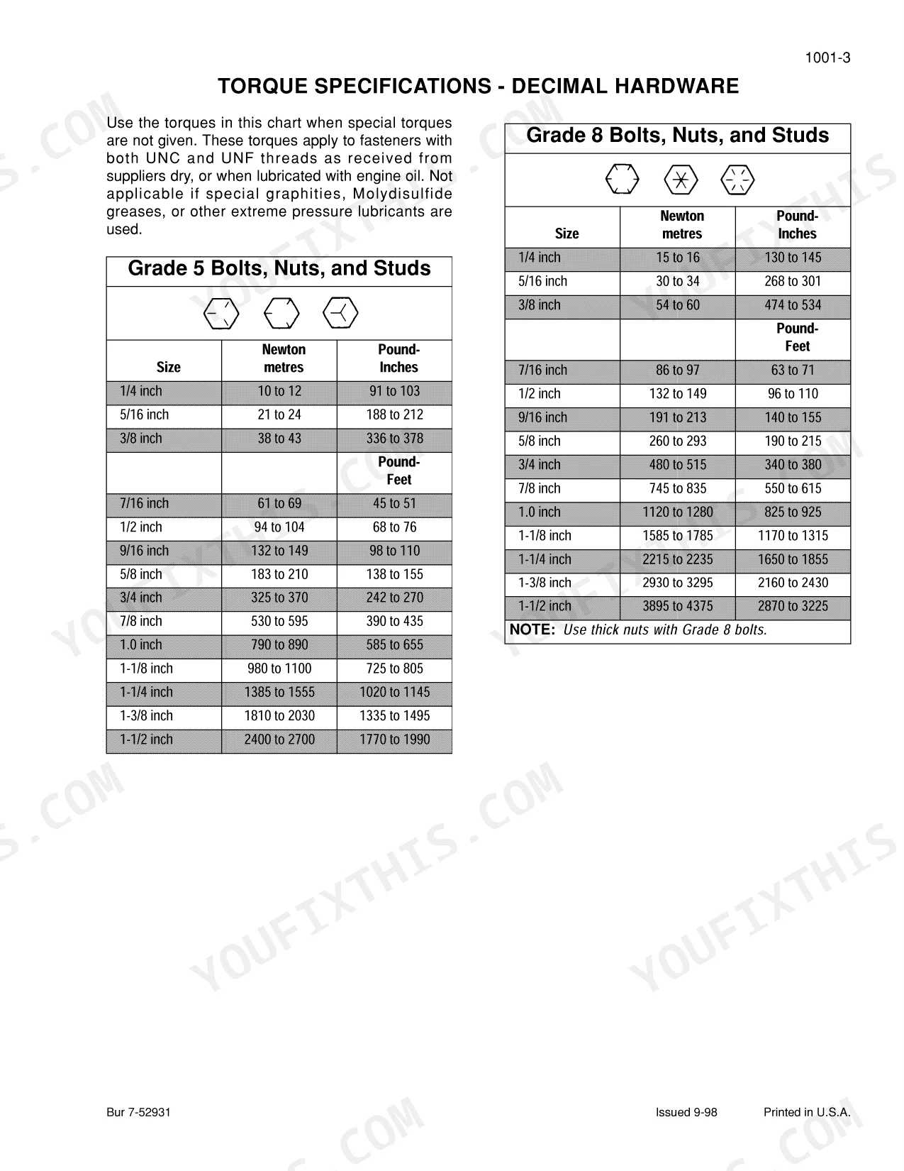
You can find standard torque specifications for decimal and metric hardware on pages 19 and 20 of the manual. Additionally, specific torque values for various components are listed within their respective sections, such as the 'Engine' (page 31) and 'Power Train' (page 217) sections. p. 17
What are the replacement specifications for the Starter motor?
The starter motor specifications are: Manufacturer: Denso, Denso part number: 428000-3140, CNH part number: SBA185086530, No-load test at 80°F (26°C): 12, Volts: 12, Rating: 2.7 KW. p. 175
What are the replacement specifications for the Parking brake solenoid/mechanism?
The parking brake solenoid/mechanism is part of the brake system. For the 410 Brake System, it is a Wet Disk, Spring Applied, Hydraulic Release type with a maximum release pressure of 1100 to 1500 kPa (11 to 15 bar) (160 to 217 psi). For the 420 Brake System, it is also a Wet Disk, Spring Applied, Hydraulic Release type with a maximum release pressure of 2760 kPa (27.6 bar) (400 psi). p. 335
What format is this manual in?
This is a 526-page searchable PDF ready for immediate download. Works on any device, so pull it up on your phone while you're under the hood. No shipping, no waiting.
Can I print this manual?
Absolutely. No DRM or copy protection. Print the whole manual or just the pages you need. Any home or office printer works.
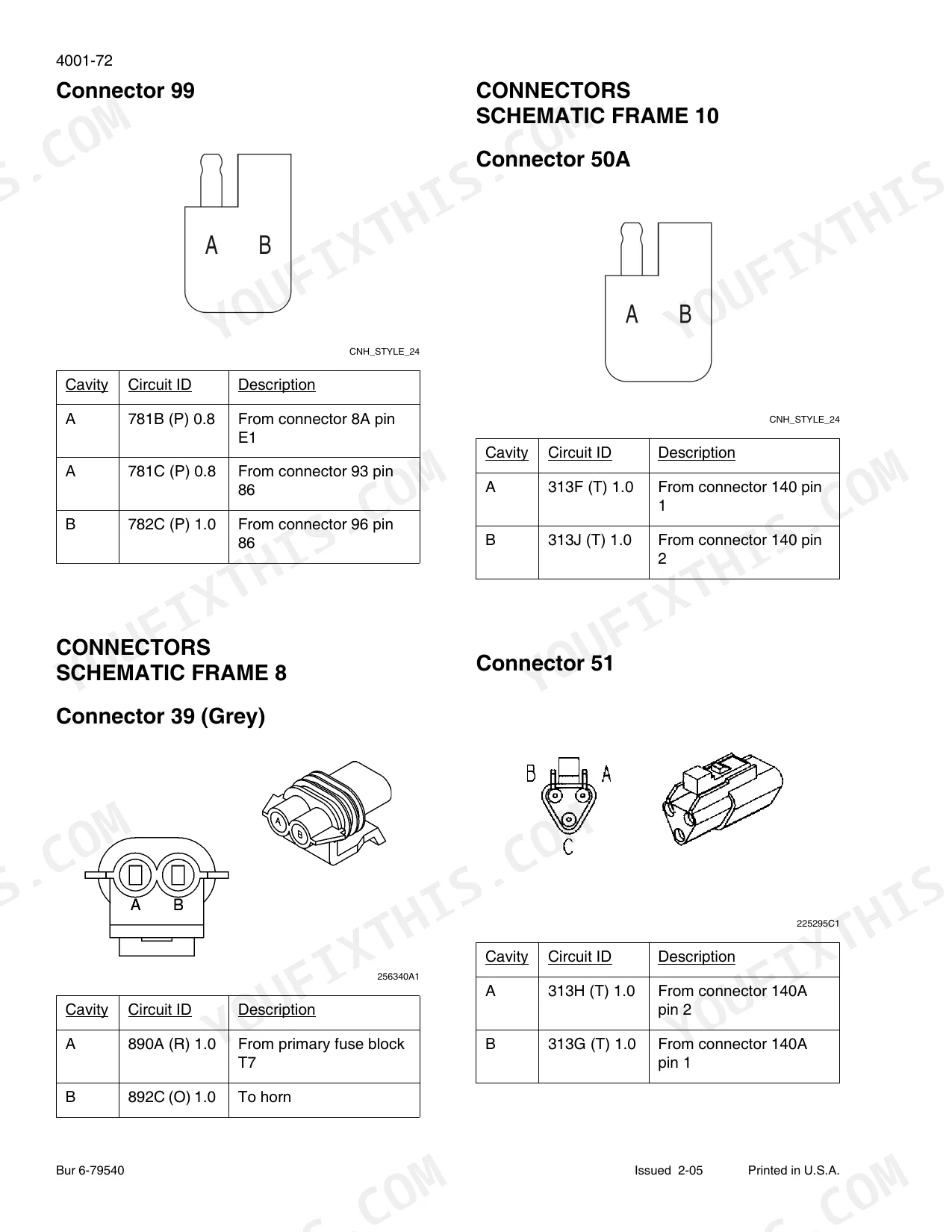
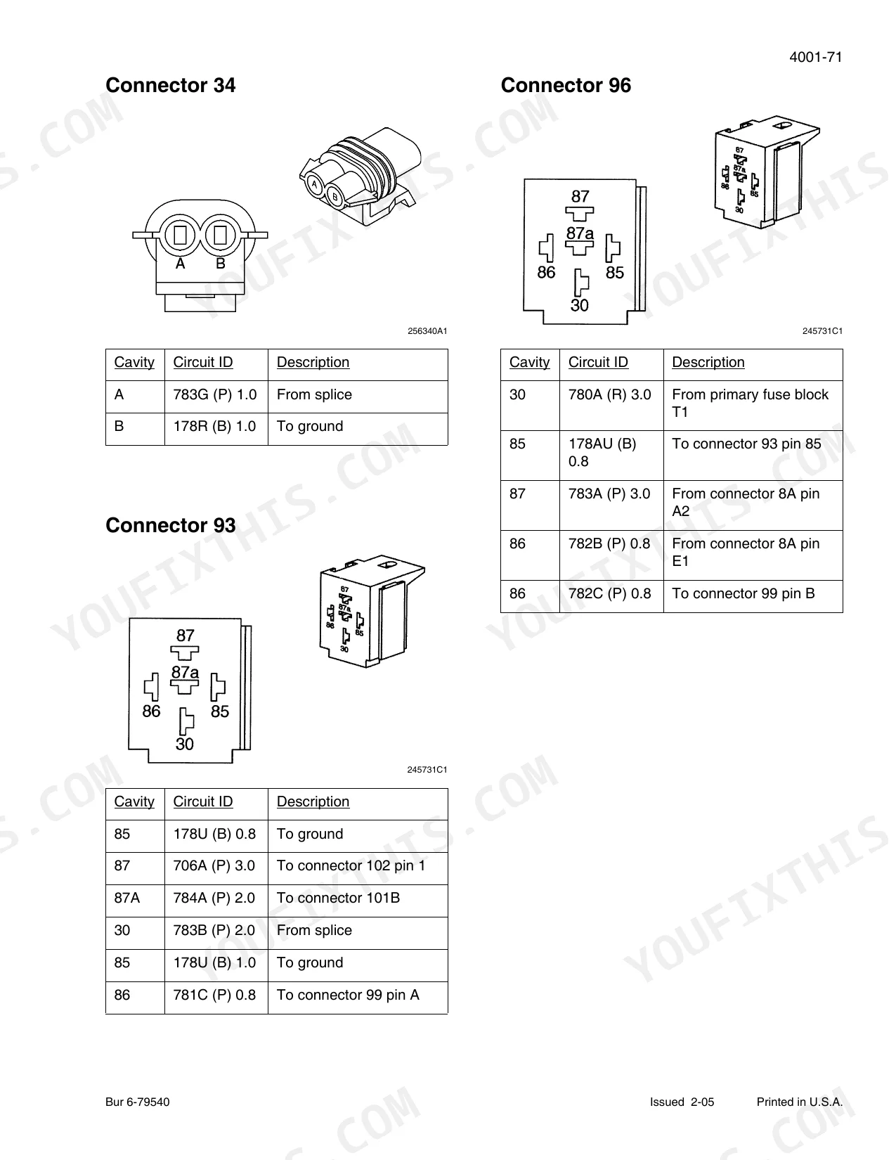
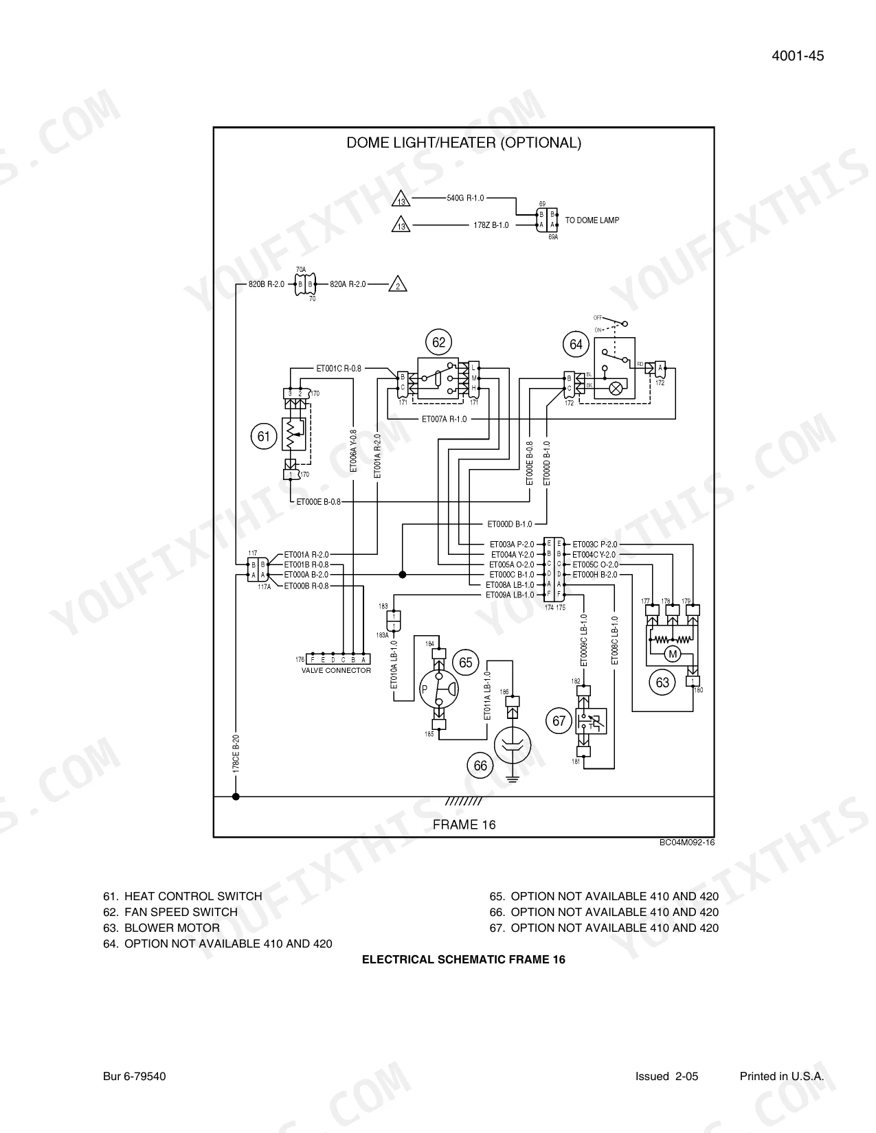
Can I find wiring schematics in this Case 410, 420, 420CT manual?
Yes, this Case 410, 420, 420CT Service Manual includes complete electrical wiring diagrams, wire routing, and connector pinouts.


Reviews
There are no reviews yet.