
Part of the Case Repair Manuals.
Case publication 7-88436R0, the factory service manual for the 2100 and 2300 series Axial-Flow combines, 2,827 pages.
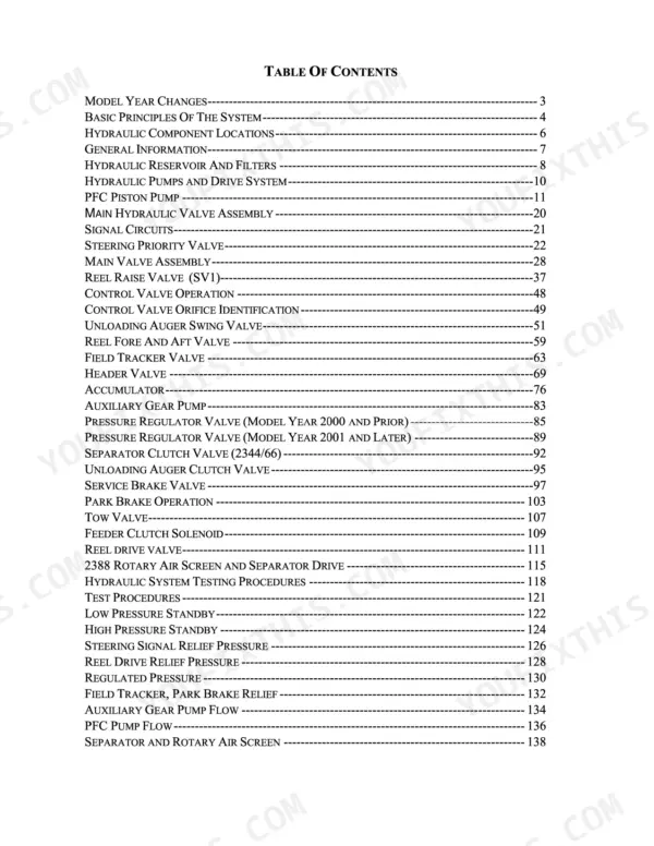
The schematics call out the 2144, 2166, 2188, 2366 and 2388 by P.I.N. range. Case numbers its chapters by system family and the book follows that: general torque and fluids, engine removal and installation, the electrical system (a large How It Works theory section, the model-year 2001 lighting circuit, then a wiring schematics and troubleshooting section running from page 581 to 1150 with connector location photographs, plus the neutral start switch, feeder reverser motor, battery servicing and alternator), steering by hand pump, cylinders, axles and the Power Guide Axle, the hydrostatic drive and transmission from theory through testing to pump and motor overhaul, brakes, hydraulics with their own How It Works and schematics chapters, and finally cab, air conditioning and separator systems.
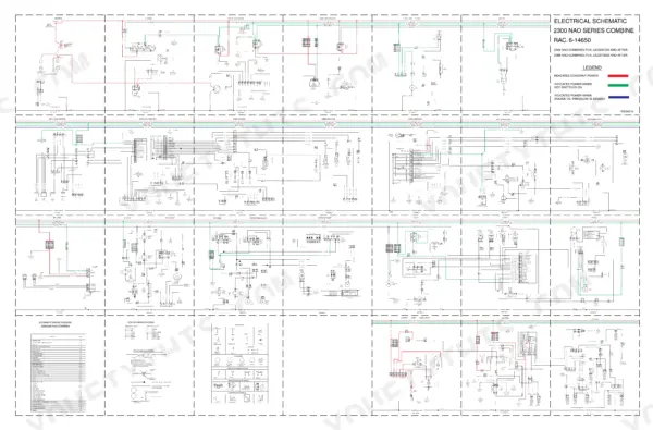
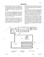
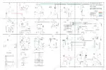
Two pages worth naming because they are why people buy this book: page 1149 is a full colour electrical schematic for the 2300 NAO series (drawing RAC. 6-14650) with a colour legend for constant power, key-switched power and oil-pressure-sensed power, and page 1500 is the hydrostatic drive schematic (drawing Rac 7-63520) with lettered test points A to E.
What's Inside This Case 2100/2300 Series Manual
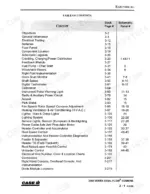
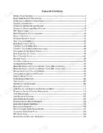
| System | Pages | Key Topics |
|---|---|---|
| General - Torque Specifications, Fluids and Lubricants | 1-16 | Standard Torque Specifications |
| Engine Removal and Installation | 17-40 | |
| Electrical System - How It Works | 41-554 | 2300 Series Axial-Flow Combines, Electrical, 2344 Combine P.I.N. Jjc0174260 and After, 2366 Combine P.I |
| Electrical System - Model Year 2001 Lighting Circuit | 555-580 | |
| Electrical System - Wiring Schematics and Troubleshooting | 581-1216 | Neutral Start Switch and Correct Starting Procedure Using, Feeder Reverser Motor, Battery Servicing and Testing, Alternator, 2100 Series Combines, And 2188 Nao Combines, P.I.N. Numbers As Speci |
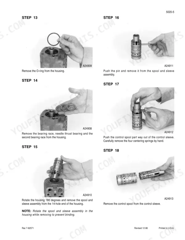
| Steering - Hand Pump, Cylinders, Axles and Power Guide Axle | 1217-1324 | Steering Axles, Except Power Guide Axle, Steering Priority Valve |
| Hydrostatic Drive and Transmission | 1325-1762 | Hydrostatic Operation, Hydrostatics, Hydrostatic Drive System Troubleshooting, Testing the Hydrostatic Drive System, Foot-N-Inch Valve, Hydrostatic Drive Pump, Removal and Installation |
| Brakes | 1763-1804 | Brake Assemblies, Removal and Overhaul, Master Brake Valve, European Park Brake Valve |
| Hydraulics - How It Works, Schematics and Troubleshooting | 1805-2272 | Hydraulic Feeder Reverser Drive, Accumulator, Hydraulic Schematics and Troubleshooting, Pressure Regulator Valve, Auxiliary Gear Pump and Pfc Pump, Main Hydraulic Valve Stack |
| Cab, Air Conditioning and Separator Systems | 2273-2827 | Air Conditioning and Troubleshooting, Air Conditioning System, Air Conditioner System Service for Systems with R-134A Ref, Air Conditioning Components Service for Systems with with, Separator Drive Jackshaft, Rotor Drive |
Case 2100/2300 Series Common Problems This Manual Covers
Feeder plugs and the reverser will not clear it, or the reverser motor does not run at all.
The reverser lives in two chapters. The hydraulics section covers the hydraulic feeder reverser drive and accumulator, while the electrical troubleshooting section has a procedure for the feeder reverser motor circuit, so you can separate a hydraulic fault from a wiring fault before pulling anything apart.
Manual Section: Hydraulics - How It Works, Schematics and TroubleshootingHydrostatic drive is sluggish, will not pull under load, or creeps in neutral.
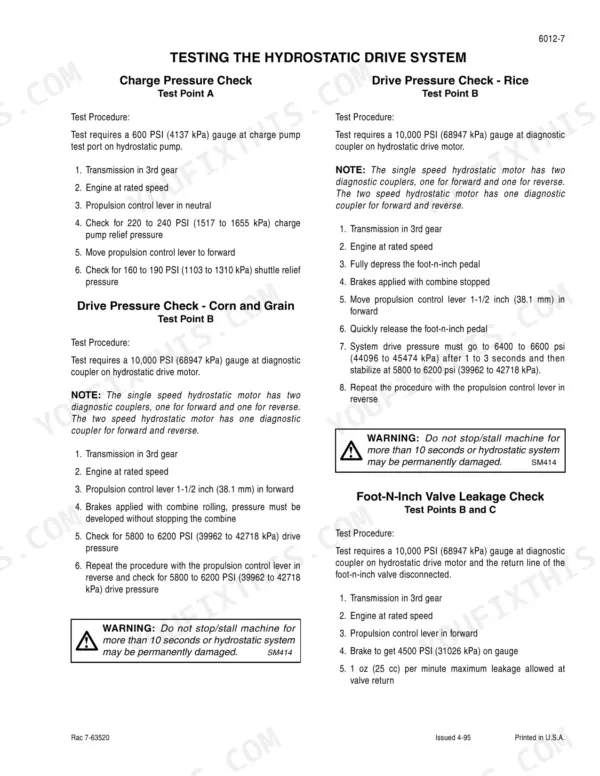
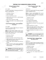
Start with the hydrostatic troubleshooting chart, then run the factory test procedure against the drive schematic using the lettered test points A through E. Charge pressure, the 40 psi bypass valve and the foot-n-inch valve are all covered before you condemn the pump or motor.
Manual Section: Hydrostatic Drive and Transmission p. 1325Brakes are soft, pull to one side, or the European park brake will not hold on a slope.
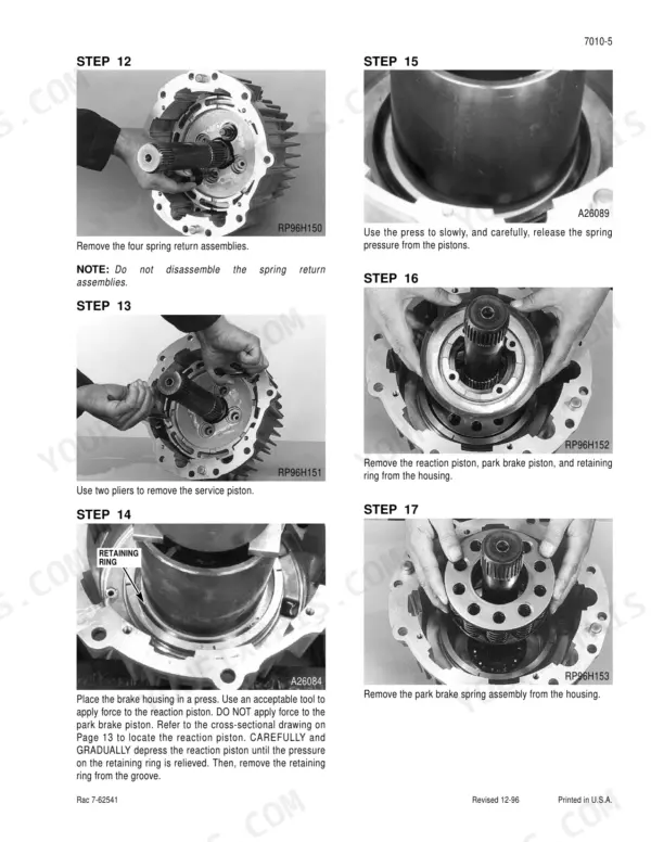
The brakes chapter walks through removal and overhaul of the brake assemblies, plus service of the master brake valve and the European park brake valve, so both the friction side and the valve side of a braking complaint are covered in one place.
Manual Section: BrakesHeader lift or another hydraulic function is slow or dead, and you do not know which valve to blame.
Work the hydraulic schematics and troubleshooting procedures through the pressure regulator valve, the auxiliary gear pump and PFC pump, and the main hydraulic valve stack. The How It Works portion explains flow through the system first, which makes the schematic actually readable.
Manual Section: Hydraulics - How It Works, Schematics and TroubleshootingFrequently Asked Questions
Does it have actual wiring schematics, or just block diagrams?
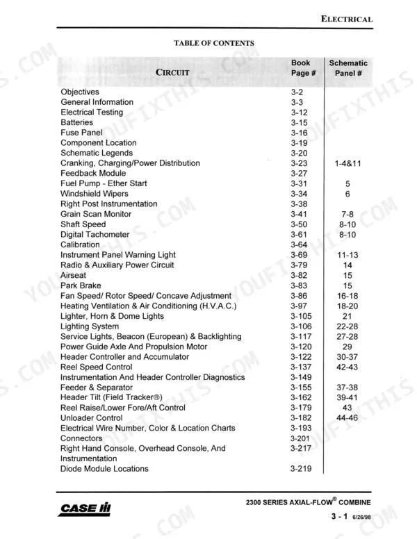
Real ones. Section 4002 is a wiring schematics and troubleshooting section running from page 581 to 1150, with photographs showing where the connectors physically sit on the machine. There is also a full colour electrical schematic for the 2300 NAO series (drawing RAC 6-14650) with a colour legend - red is constant power, green is power with the key on, blue is power when engine oil pressure is sensed - plus a circuit index covering cranking, power distribution, instrumentation, lighting, HVAC, rotor speed and concave adjust. Schematics are split by model and P.I.N. break, so check that your serial number range is called out, for example 2344 P.I.N. JJC0174260 and after. p. 1149
Will this help me diagnose a weak or jerky hydrostatic drive?
Yes, and it is one of the strongest parts of the book. The hydrostatic chapter covers operation theory, a troubleshooting chart, and a full test procedure with a drive schematic (drawing RAC 7-63520) showing the charge pump, the 40 psi bypass valve, the foot-n-inch valve and the fixed displacement motor, with lettered test points A through E so you can put a gauge on the system instead of guessing. Pump removal and installation is covered separately. p. 1325
My combine cranks fine in the shop but the starting circuit acts up in the field. Is the neutral start system covered?
It is. The wiring and troubleshooting section has a specific procedure for the neutral start switch and the correct starting procedure, alongside battery servicing and testing and alternator diagnosis. Since a dead-crank complaint on these machines is usually a switch, a ground or a tired battery rather than the starter itself, having the factory test sequence saves you from throwing parts at it. p. 1151
Does it cover the air conditioning system, and is it the R-134a system?
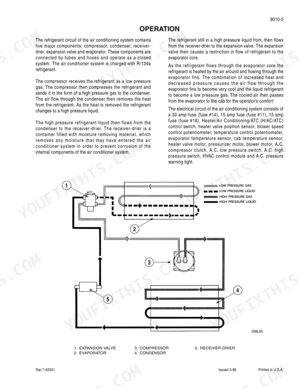
Yes. The cab chapter includes air conditioning troubleshooting plus dedicated service coverage for systems with R-134a refrigerant, both the system-level service and the individual components. If your cab is heat-soaking you during harvest, the diagnostic side of that chapter is where to start before you pay someone to gas it up again. p. 2273
How is the manual organized? 2,827 pages sounds hard to navigate.
Case numbers the chapters so the leading digit tells you the system family: 1000s are general and torque specs, 2000s engine, 4000s electrical, 5000s steering, 6000s hydrostatic drive and transmission, 7000s brakes, 8000s hydraulics, 9000s cab, air conditioning and separator. Once you know that, you can jump straight to the system you are working on. The theory sections up front are worth reading once before you ever chase a fault.









