

Part of the Case Operator Manuals.
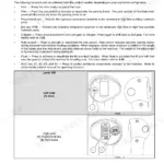
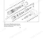
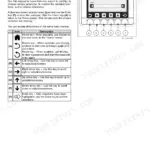
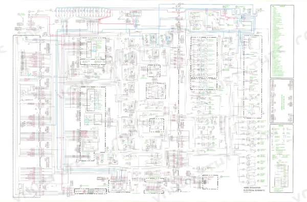
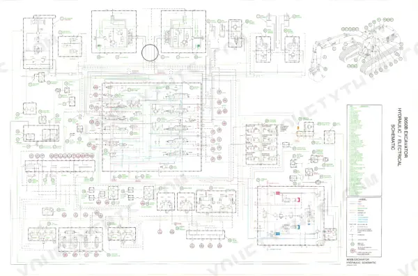
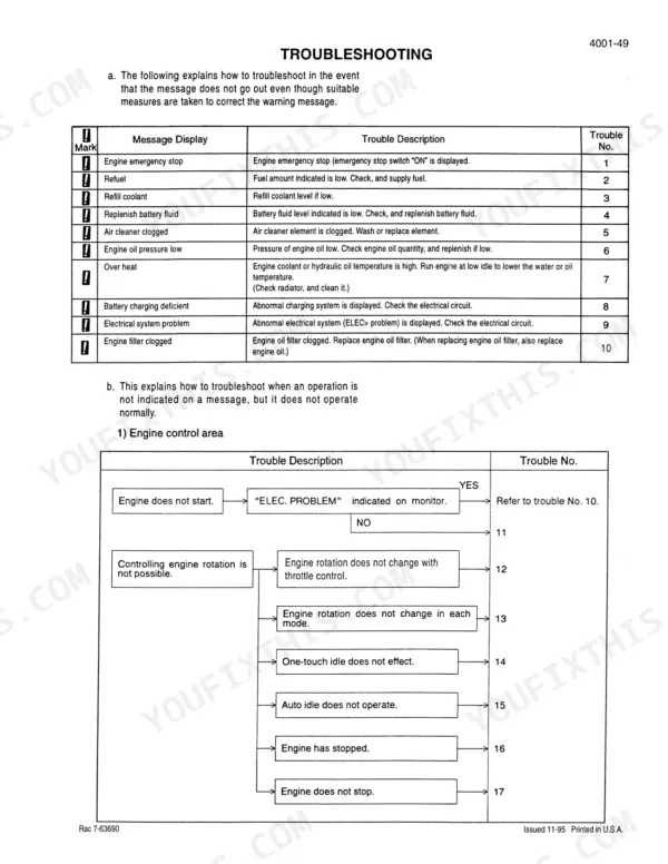
Every one of the 785 pages in this official Case Corporation 9050B Service Manual PDF (OEM #7-64192) zeroes in on tearing down and rebuilding your heavy-duty excavator. You get full hydraulic schematics mapping the main pumps to the bucket control valves, foldout wiring diagrams for tracing elusive electrical faults, and extensive troubleshooting charts to decode complex error codes quickly. Inside, find step-by-step procedures covering everything from the final drive transmission and swing motor to the track recoil spring assembly and boom cylinders. Top off the engine crankcase with exactly 29.3 liters of oil and verify that new compressor belt is tensioned between 95 and 115 lbs before you even think about starting the ignition. Equipment downtime drains your budget fast. Download this digital copy, tap through the bookmarked chapters right on your shop tablet, and get your machine back in the dirt.
What's Inside This Case Corporation 9050B Manual
| System | Pages | Key Topics |
|---|---|---|
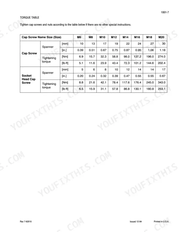
| General | 4-31 | Safety, General Information and Torque Specifications, Specifications |
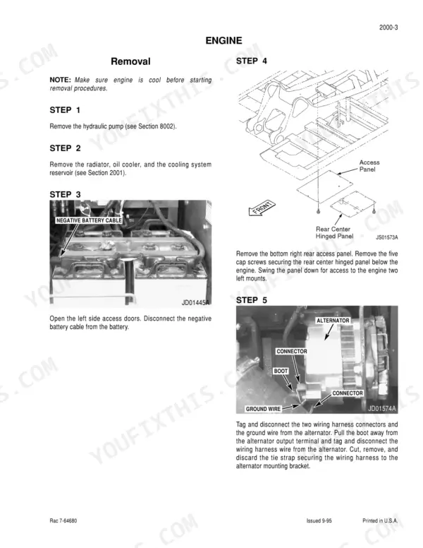
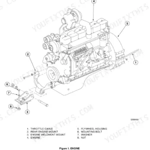
| Engines | 32-69 | Engine, Radiator, Oil Cooler and Cooling System Reservoir |
| Fuel System | 70-81 | Fuel Tank, Filters and Lines |
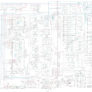
| Electrical | 82-159 | Electrical Specifications and Troubleshooting, Electrical Schematic Foldout |
| Tracks | 160-219 | Sprocket, Track Roller, Carrier Roller, Idler Wheel, Recoil Spring Assembly, Track Adjustment Cylinder |
| Power Train | 220-275 | Drive Motor, Final Drive Transmission, Swing Motor, Swing Reduction Gear Assembly |
| Hydraulic System Overview & Maintenance | 276-347 | Specifications, Special Tools, General Information, Contamination & Cleaning, Pressure Testing, Troubleshooting |
| Hydraulic Pumps & Main Control Valve | 348-385 | Main Hydraulic Pump, Hydraulic Pump Coupling, Pilot Pump, Main Hydraulic Control Valve |
| Cylinders and Associated Controls | 386-545 | Boom, Arm, And Bucket Cylinders, Hand & Foot Control Valves, Shuttle Valve, Accumulator, Solenoid Valves, Cushion Control Valve |
| Auxiliary Hydraulic System | 546-563 | General Information, Boom Arm Shutoff Valves, Auxiliary Hydraulics Return Filter, Relief & Shutoff Valve, Flow Control Valve, Flow Combining Valve |
| Hydraulic Reservoir & Filtration | 564-619 | Reservoir Pressurization, Air Tank & Governor, Hydraulic Pilot Filter, Hydraulic Inline Filter, Bypass Oil Filter, Hydraulic Swivel |
| Mounted Equipment | 620-783 | Upper Structure, Counterweight, Boom, Arm, Bucket, Cab |
| Hydraulic and Electrical Schematic | 784-785 | Hydraulic System Schematic Foldout, Electrical Wiring Schematic Foldout, Circuit and Component Reference Diagrams |
Quick Reference Specifications
| Specification | Value | Page |
|---|---|---|
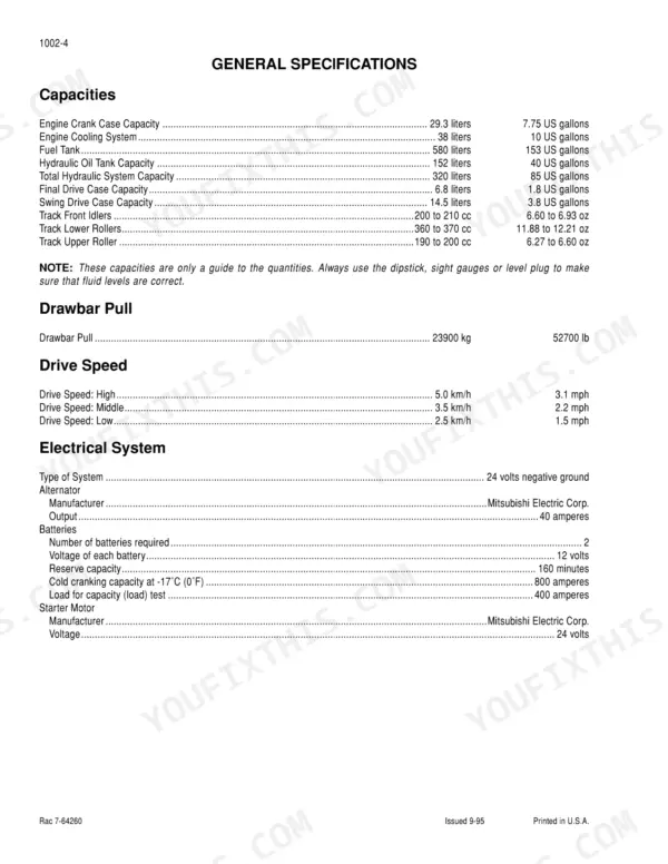
| Engine Crank Case Capacity | 29.3 liters | p. 17 |
| Fuel Tank Capacity | 580 liters | p. 17 |
| Hydraulic Reservoir Refill Capacity | 40 gallons | p. 278 |
| Total Hydraulic System Capacity | 85 gallons | p. 278 |
| Compressor New Belt Tension | 95 to 115 lbs | p. 746 |
| Fuel Filter Service Interval | replace every 500 hrs | p. 71 |