
Part of the Case Repair Manuals.
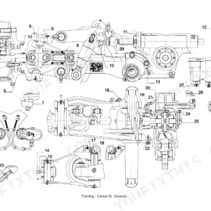
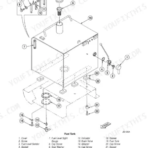
This is the complete Case factory service manual for the 621C and 721C wheel loaders. It is organized into the standard Case service groups, General, Engines, Electrical, Steering, Power Train, Brakes, Hydraulics, and Mounted Equipment, and it includes the electrical schematics and wiring coverage. Each group carries specifications, pressure checks, troubleshooting, and step-by-step removal, disassembly, inspection, assembly, and installation procedures, including the air conditioning system, the ride-control hydraulics, and the Information and Diagnostics Center, for both the 621C and 721C.
Other editions of this manual
- Case 621C, 721C, 921C Loader Service Manual (Incl. Wiring) $49.95
- Case 721C 821C Wheel Loader Service Manual (incl. Wiring) Original price was: $60.99.$39.99Current price is: $39.99.
What's Inside This Case 621C, 721C, 621C/721C Manual
| System | Pages | Key Topics |
|---|---|---|
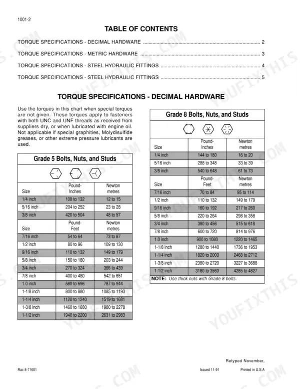
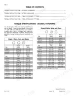
| General | Standard Torque Specifications, Fluids and Lubricants | |
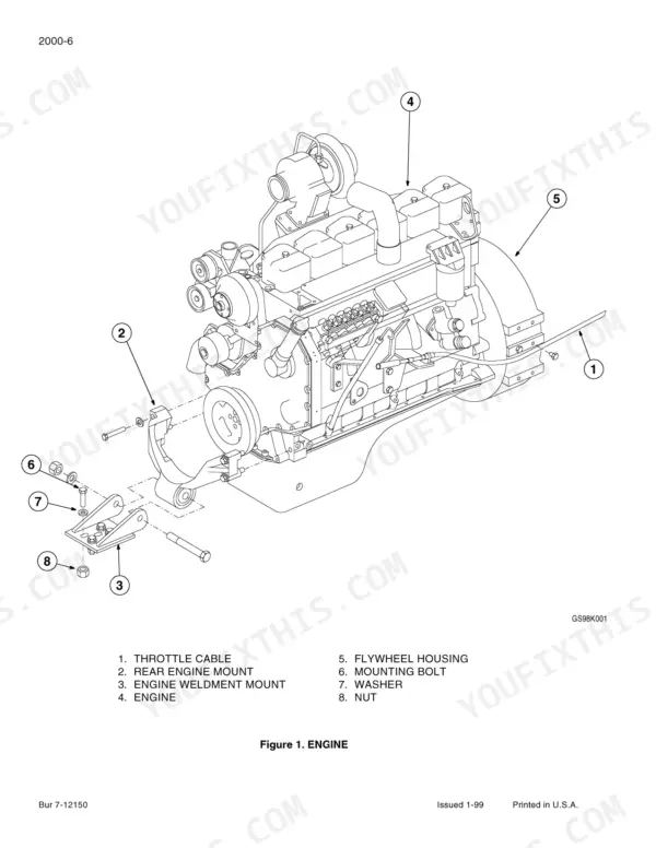
| Engines | Engine and Radiator Removal and Installation, Stall Tests | |
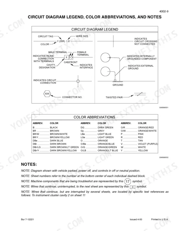
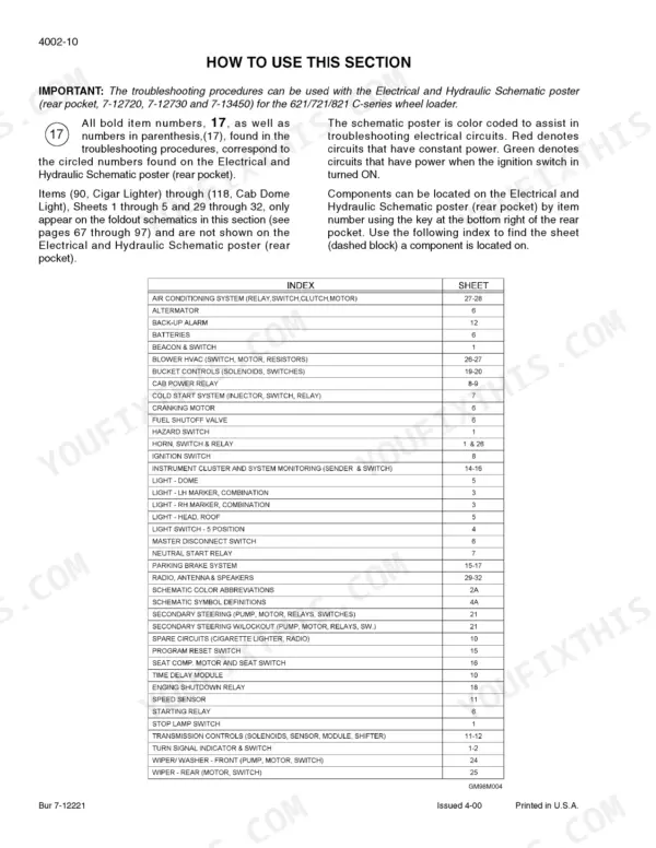
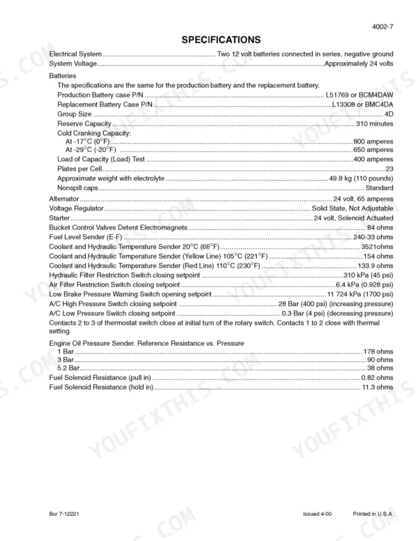
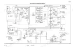
| Electrical | Removal and Installation of Starter and Alternator, Electrical Specifications, Troubleshooting, And Schematics, Battery(S), Starter and Starter Solenoid, Information and Diagnostics Center, Alternator | |
| Steering | Removal and Installation of Steering Components, Steering Specifications, Pressure Checks, And Troubleshooting, Steering Control Valve, Steering Priority Valve, Steering Cylinder, Center Pivot | |
| Power Train | Transmission Specifications, Pressure Check, And Troubleshooting, Transmission, Drive Shaft, Center Bearing, And Universal Joints, Wheels and Tires, Transmission Control Valve | |
| Brakes | Removal and Installation of Brake Components, Hydraulic Brake Troubleshooting, Brake Accumulators, Brake Actuator Valve, Brake Accumulator Valve, Parking Brake | |
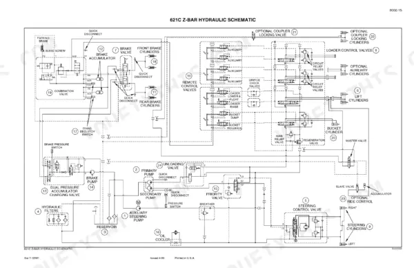
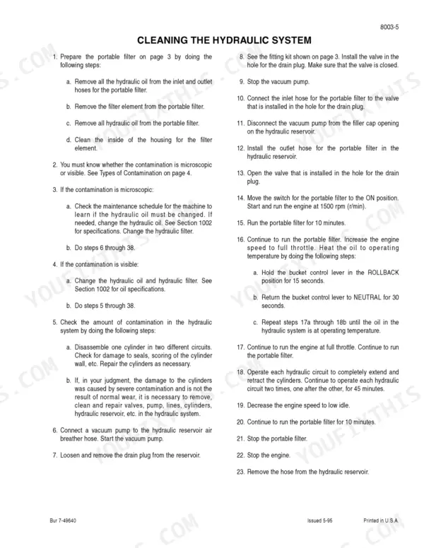
| Hydraulics | Removal and Installation of Hydraulic Components, Hydraulic Specifications, Troubleshooting, And Pressure Checks, Cleaning the Hydraulic System, Hydraulic Pump, Loader Control Valve, Cylinders, Coupler Lock Valve, Remote Control Valves, Combination Valve, Accumulator for Ride Control, Solenoid Valve and Accumulator Valve for Ride Control | |
| Mounted Equipment | Pedals and Levers, Air Conditioning Troubleshooting and System Checks, For Systems Wi, Air Conditioner System Service, Removal and Installation of Air Conditioning Components, For Syste, Air Conditioning Compressor and Clutch, Loader, ROPS Cab and ROPS Canopy, Cab Glass Installation |
Quick Reference Specifications
| Specification | Value | Page |
|---|---|---|
| All Models | ||
| Low brake pressure warning switch actuation pressure | 110 to 124 bar (1600 to 1800 psi) | p. 505 |
| Engine oil pressure warning actuation threshold | below 100 kPa (14.5 PSI) | p. 221 |
| Standard Torque, Grade 8 Bolts, 1/4 inch | 144 to 180 pound-inches | p. 8 |
| Batteries Cold Cranking Capacity at 0°F | 800 amperes | p. 75 |
| Alternator Output | 28 volts at 65 amperes | p. 234 |
| Steering Relief Valve Pressure Setting | 184 to 193 bar (2665 to 2800 psi) | p. 256 |
| Transmission Main Pressure and Clutch Pressure | 16 to 18 bar (230 to 265 psi) | p. 297 |
| Ride Control Accumulator Dry Nitrogen Pressure | 31 ±1.7 bar (450 ±25 psi) | p. 699 |
| Air Conditioning System Refrigerant Capacity | 1.6 kg (3.5 lbs) | p. 748 |
| 621C/721C | ||
| Number of Teeth on Flywheel | 127 | p. 51 |
| 621C/921C | ||
| Brake Pump Output | 27.4 L/min at 172 bar | p. 505 |
Case 621C, 721C, 621C/721C Common Problems This Manual Covers
Case 621C loader battery keeps dying overnight and warning lights flicker during operation
Check the alternator output as detailed on page 234. Connect a multimeter and verify the system is charging at exactly 28 volts at 65 amperes at full throttle. Inspect the wiring harness for loose connections. Replace the alternator if output falls below specification.
Manual Section: Section 4007, Alternator p. 234Heavy resistance when turning the steering wheel at low speeds or at idle
Install a pressure gauge on the steering test port. Start the engine and verify the steering relief valve pressure setting is between 184 to 193 bar (2665 to 2800 psi) as specified on page 256. Adjust the priority valve if pressure is out of range.
Manual Section: Section 5002, Steering Specifications, Pressure Checks, and Troubleshooting p. 256Transmission slips out of gear under heavy load or takes too long to engage
Connect a gauge to the transmission test ports to check the main and clutch pressure. Verify the readings match the 16 to 18 bar (230 to 265 psi) specification on page 297. Drain the fluid and clean the transmission control valve if pressure drops.
Manual Section: Section 6002, Transmission Specifications, Pressure Check, and Troubleshooting p. 297Low brake pressure warning alarm stays on constantly after the engine is started
Test the low brake pressure warning switch actuation pressure to confirm it triggers correctly between 110 to 124 bar (1600 to 1800 psi). Reference page 505 for the exact test port locations. Inspect the brake pump and accumulator charge valve for internal leaks.
Manual Section: Section 7002, Hydraulic Brake Troubleshooting p. 505Cab air conditioning blows warm air or compressor cycles on and off repeatedly
Recover the existing freon and evacuate the system using proper manifold gauges. Weigh the exact charge and fill the system to the standard air conditioning system refrigerant capacity of 1.6 kg (3.5 lbs) as noted on page 748. Check the compressor clutch operation.
Manual Section: Section 9003, Air Conditioner System Service p. 748Frequently Asked Questions
Does this manual cover the engine on my 621C or 721C?
The Engines group covers engine and radiator removal and installation and the stall tests for both the 621C and 721C, along with the specifications you need to set them up. It is a chassis and systems service manual, so deep internal engine rebuild is handled in the matching Case engine service manual, which this book cross-references.
My loader has weak or slow hydraulics. Where do I look?
Go to the Hydraulics group: it has hydraulic specifications, troubleshooting, and pressure checks, plus the hydraulic pump, loader control valve, cylinders, combination valve, and the ride-control accumulator and its solenoid and accumulator valves. Verify pump and relief pressures against spec before replacing any valve, and check the ride-control circuit if the boom bounces or drifts.
The machine will not steer properly or feels heavy. What should I check?
The Steering group walks steering specifications, pressure checks, and troubleshooting, then the steering control valve, steering priority valve, steering cylinder, and center pivot. Confirm priority-valve and control-valve pressures before condemning the cylinder or pump, since a priority-valve fault starves the steering circuit.
How are the brakes and accumulators serviced?
The Brakes group covers removal and installation of brake components, hydraulic brake troubleshooting, the brake accumulators and accumulator valve, the brake actuator valve, and the parking brake. It includes the nitrogen pre-charge, disassembly, inspection, and assembly steps for the accumulators, which is the usual cause of a spongy or fading brake pedal.
Does it include the electrical schematics and diagnostics?
Yes. The Electrical group covers electrical specifications, troubleshooting, and schematics, the batteries, starter and solenoid, alternator, and the Information and Diagnostics Center with its indicators, warning displays, and diagnostic settings, so you can read the machine's own fault indications and trace the circuits.
How is this Case 621C Service Manual delivered?
Instant PDF download (172 MB). You get the full 824-page searchable Service Manual immediately after payment. Open it on your laptop, tablet, or phone right in the shop.
Can I print specific sections of this Case 621C Service Manual?
No restrictions at all. Print individual pages, full chapters, or the entire manual. The PDF is completely unlocked.









