
Part of the Case Operator Manuals.
Every one of the 657 pages in this Case CX135SR Service Manual PDF (OEM #SM135SRTOC-0EN) is aimed at one machine: the CX135SR crawler excavator, standard and Tier 3. You get full-size electrical and hydraulic schematics (pp. 655-657), a dedicated troubleshooting section with pressure measurement and flow curve procedures, and step-by-step teardown coverage for the main pump, control valve, swing motor, final drives, and every attachment cylinder. Inside: undercarriage work too, from track removal to take-up rollers. Set the main relief valve at 34.3 MPa for boom, arm, and bucket circuits, then torque the turntable bearing bolts to 280-312 Nm. Your excavator is parked and the meter is running. Get factory numbers, not forum guesses. Bookmarked PDF that opens on any device; type a spec into the search bar and jump straight to the right section.
What's Inside This Case CX135SR Manual
| System | Pages | Key Topics |
|---|---|---|
| General Information | 3-56 | Safety, General Information and Standard Torque Data |
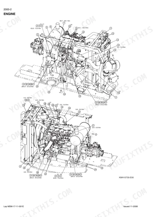
| Engine | 57-60 | Removal and Installation of the Engine, Engine Specifications, Disassembly and Assembly of the Engine |
| Fuel System | 61-64 | Removal and Installation of the Fuel Tank, Fuel Engine System |
| Electrical System | 65-146 | Electrical and Engine Functions and Service Support |
| Undercarriage | 147-196 | Removal and Installation of Tracks, Rollers, Take-Up Roller |
| Drive Train | 197-262 | Removal and Installation of the Drive Motor and Final Drive Transmission, Disassembly and Assembly of the Drive Motor and Final Drive Transmission |
| Specifications, Troubleshooting, and Hydraulic Pressure Settings | 263-288 | Hydraulic Pressure Settings, Troubleshooting, Pressure Measurement, Flow Curve |
| Hydraulic Reservoir and Main Pump | 289-324 | Hydraulic Reservoir Removal, Main Hydraulic Pump Removal, Main Hydraulic Pump Disassembly, PTO Unit |
| Main Hydraulic Control Valve | 325-406 | Control Valve Disassembly, Control Valve Assembly, Relief Valves, Anti-Drift Valves |
| Attachment Cylinders | 407-470 | Boom Cylinder, Dipper Cylinder, Bucket Cylinder, Offset Cylinder, Blade Cylinder |
| Hand Control Levers and Foot Control Pedals | 471-522 | Hand Control Lever Disassembly, Foot Control Pedal Disassembly, Pilot Function Blocks |
| Solenoid Valves and Cushion Control Valve | 523-558 | Solenoid Valve Block, Cushion Control Valve, Hydraulic Swivel |
| Hydraulic Functions and Component Functions | 559-648 | Travel Circuits, Swing Circuits, Boom Circuits, Arm Circuits, Option Circuits |
| Upperstructure | 649-657 | Air Conditioning Unit, Large Size Hydraulic Schematics, Large Size Hydraulic Schematics - 2PC and Dozer Blade, Large Size Electrical Schematics |
Quick Reference Specifications
| Specification | Value | Page |
|---|---|---|
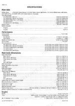
| Set pressure of main relief valve (Boom/Arm/ Bucket) | 34.3 MPa (4974.79 psi) | p. 21 |
| Set pressure of main relief valve (Swing) | 28.0 MPa (4061.06 psi) | p. 21 |
| Swing motor operating pressure | 28 MPa (4061 psi) | p. 26 |
| Swing motor mechanical brake torque | 284.7 Nm (209.98 lb-ft) | p. 26 |
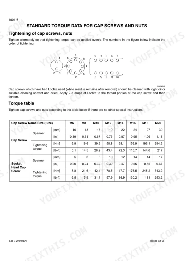
| Turntable bearing (lower frame) torque setting | 280-312 Nm (206-230 lb-ft) | p. 48 |
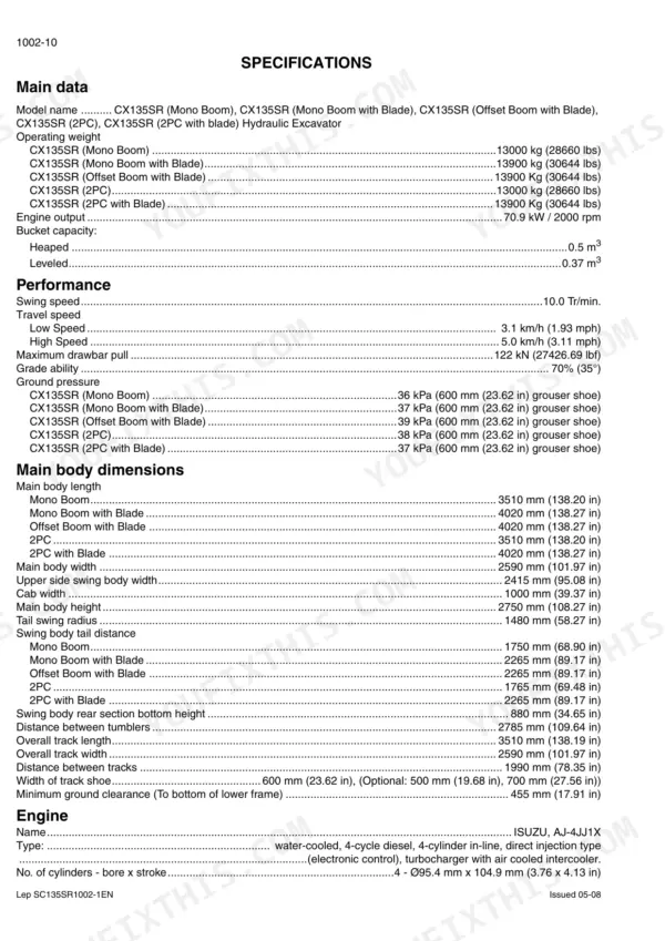
| Engine Output | 70.9 kW / 2000 rpm | p. 18 |
| Hydraulic Oil Tank Capacity | 81 L | p. 19 |
| Engine Oil Capacity | 17.2 L | p. 19 |
| Main Relief Valve Pressure | 34.3 MPa | p. 21 |
| Swing Relief Valve Pressure | 28.0 MPa | p. 21 |
| Travel Motor Relief Valve Pressure | 37.3 MPa | p. 26 |
| Swing Motor Relief Valve Pressure | 28 MPa | p. 26 |
Case CX135SR Common Problems This Manual Covers
Case CX135SR slow hydraulics and weak bucket response after warm-up, boom drifts down under load
Check main relief pressure at the P1 and P2 ports; the set pressure is 34.3 MPa (4974 psi), listed on page 21. Measure with the machine at operating temperature using the pressure procedures that start on page 263. If pressure is low, inspect the pilot filter and relief valve seats before condemning the pump.
Manual Section: Specifications, Troubleshooting, and Hydraulic Pressure Settings p. 263No response on boom, arm, or bucket from either joystick, travel still works
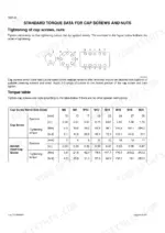
Verify pilot supply first; a clogged pilot filter starves every function at once. Test secondary pressure at each joystick output port; if it will not rise or is unstable, disassemble the hand control lever using the procedure starting on page 471. On reassembly, torque M10 cap screws to 39.2 Nm per the chart on page 8.
Manual Section: Hand Control Levers and Foot Control Pedals p. 471Swing is jerky and will not hold position on a slope, upper structure creeps
Measure swing circuit pressure; the swing motor relief valve is set at 28 MPa (4061 psi), shown on page 26. If relief pressure checks good, inspect the swing motor mechanical brake; minimum holding torque is 284.7 Nm. Check the turntable bearing bolts, torqued to 280-312 Nm on page 48, before condemning the slew bearing.
Manual Section: Swing Motor and Swing Reduction Gear Troubleshooting p. 26Engine cranks but runs rough and loses power under load, white smoke at idle
Check for air in the fuel system and water in the fuel before chasing injectors. Bleed the lines, replace the fuel filter, and pull the lift pump inlet screen for cleaning; a restricted screen drops discharge pressure. Fuel system service starts on page 61. A healthy engine makes its rated 70.9 kW at 2000 rpm.
Manual Section: Fuel System p. 61Machine pulls to one side traveling straight, one track noticeably slower than the other
Check travel circuit pressure on the weak side first; the travel motor relief valve is set at 37.3 MPa, listed on page 26. Swap travel lines at the swivel to isolate the motor from the control valve. If the motor is at fault, drive motor and final drive removal procedures begin on page 197.
Manual Section: Travel Motor and Final Drive Troubleshooting p. 197Hydraulic oil overheats after an hour of digging, functions get spongy and slow
Drain and refill with clean oil if it smells burnt or looks milky; hydraulic tank capacity is 81 L, listed on page 19. Bleed air from the system after any refill and warm the machine up before loading it. Clean the cooler fins and check oil level daily; low oil aerates fast and cooks the pump.
Manual Section: Hydraulic Reservoir and Main Pump p. 19Frequently Asked Questions
How do I clear fault codes on a Case CX135SR?
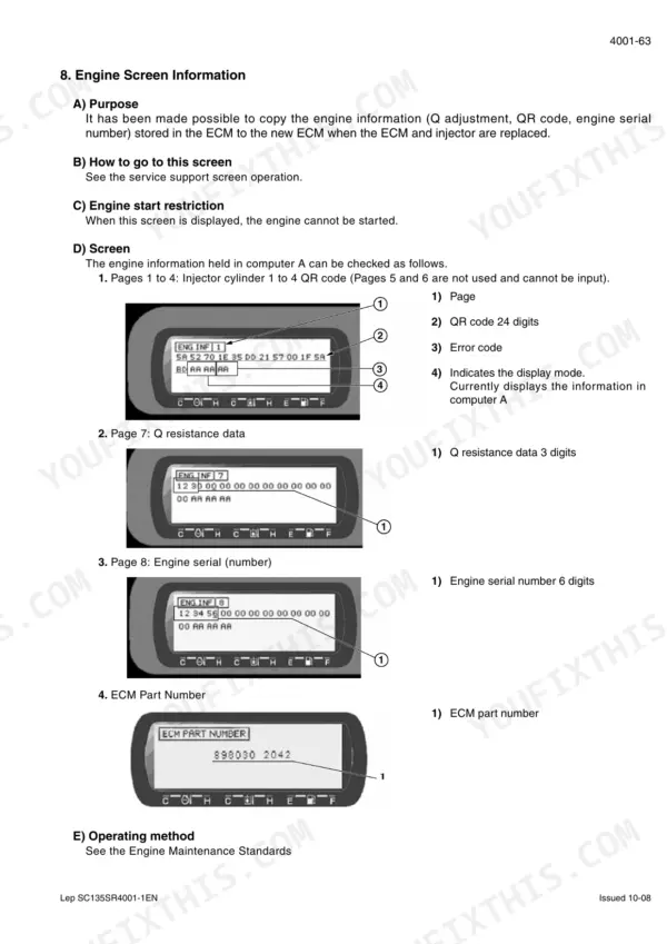
To clear fault codes, the engine controller must receive the clear memory signal (IN2) by being ON (0 V) for 1 second or longer, followed by an OFF (≠0 V) signal for 0.5 seconds or longer. p. 94
How do I enter diagnostic mode on a Case CX135SR?
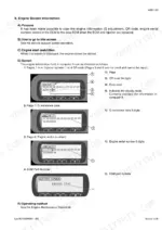
To enter the service support screen, hold down both the travel high-speed switch and the horn volume select switch on the switch panel for 3 seconds. From there, you can navigate to the DIAG (trouble diagnosis) screen. p. 96
What are the replacement specifications for the hydraulic oil pilot line filter?
The pilot line filter (inside the housing) has a filtration rating of 8 μm. p. 19
What is the tightening torque for the main relief valve on the control valve?
The main relief pressure is set to 34.3 MPa at 60 L/min. To adjust, fasten the main relief valve 180 degrees. p. 278
What is the engine oil capacity for the CX135SR?
The engine oil capacity is 17.2 liters (4.54 gallons). p. 19
What do I get after purchasing this Case CX135SR manual?
This is a 657-page searchable PDF ready for immediate download. Works on any device, so pull it up on your phone while you're under the hood. No shipping, no waiting.
Can I print a copy of this Case CX135SR Service Manual for the shop?
Print away. There is no DRM and no page limit. Many buyers print one chapter at a time and leave the rest on a tablet.







Reviews
There are no reviews yet.