
Part of the Case Repair Manuals.
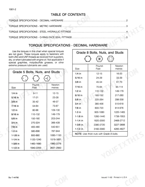
Case's 9040 service manual, OEM 7-46360, walks you through every system on the 9040 excavator across 532 factory pages. The hydraulics section runs from cleaning the system through main pump, pilot control circuit pump, hydraulic swivel, main control valve, swing motor and swing reduction gear box, cushion control valve, and boom holding valve. The electric and hydraulic schematic foldouts map circuit routing end to end, while track troubleshooting and pressure check charts let you trace a fault to the component instead of the symptom. Torque a 1/2 in Grade 5 fastener to 80-96 pound-feet (109-130 Newton metres), and expect 24 volts and 45 amperes out of the alternator. Chasing a swing or travel fault with no schematic in the cab is a long afternoon. This PDF is bookmarked by section and text-searchable, so you find the procedure and get the machine moving again.
What's Inside This Case 9040 Manual
| System | Pages | Key Topics |
|---|---|---|
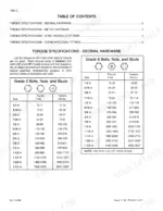
| General Information | 3-16 | Section Index - General (Standard Torque Specifications for 9000 Series Excavators, Fluids and Lubricants) |
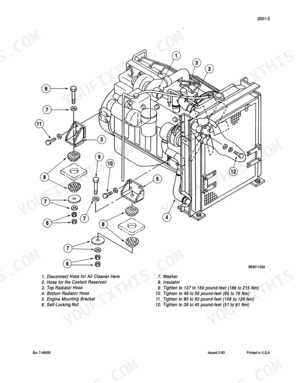
| Engines | 17-218 | Section Index - Engines (Engine Removal and Installation, Radiator Removal and Installation, Detailed Engine Specifications) |
| Fuel System | 219-270 | Section Index - Fuel System (System and Filters, Injectors, Injection Pump) |
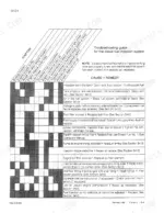
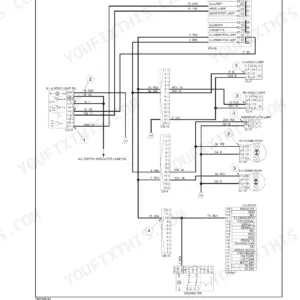
| Electrical | 271-356 | Section Index - Electrical (Electrical Specifications and Troubleshooting, Electric Schematic Foldout, Batteries, Systems Display Panel, Starter and Starter Solenoid, Alternator) |
| Tracks | 357-386 | Troubleshooting the Track System, Track, Rollers, And Idlers |
| Power Train | 387-394 | Section Index - Power Train (Troubleshooting, Drive Motor and Final Drive Transmission) |
| Hydraulics | 395-506 | Section Index - Hydraulics (Cleaning the Hydraulic System, Hydraulic Specifications, Troubleshooting) |
| Mounted Equipment | 507-532 | Section Index - Mounted Equipment (Pedals and Levers, Turntable Bearing, Boom and Arm, Seat and Seat Belts, Electric and Hydraulic Schematic Foldout) |
Quick Reference Specifications
| Specification | Value | Page |
|---|---|---|
| Grade 5 Bolts, Nuts, and Studs (1/4 in) | 9-11 Pound-Feet (12-15 Newton metres) | p. 6 |
| Grade 5 Bolts, Nuts, and Studs (5/16 in) | 17-21 Pound-Feet (23-28 Newton metres) | p. 6 |
| Alternator voltage | 24 volts | p. 277 |
| Alternator amperage | 45 amperes | p. 277 |
| Control limit switch (attachment control shutoff limit switch) voltage | 24 volts | p. 297 |
| Control switch solenoid voltage | 24 volts | p. 299 |
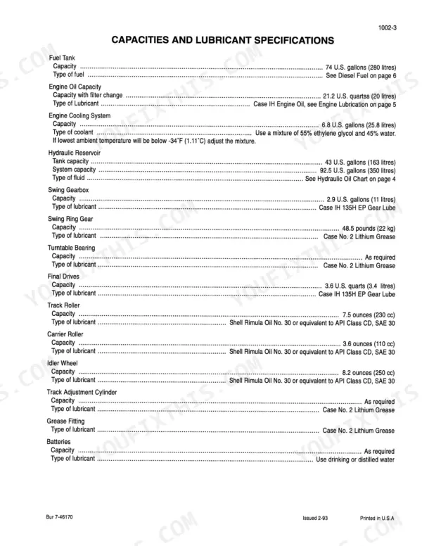
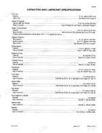
| Fuel Tank Capacity | 74 U.S. gallons (280 litres) | p. 13 |
| Engine Oil Capacity with filter change | 21.2 U.S. quarts (20 litres) | p. 13 |
| Engine Cooling System Capacity | 6.8 U.S. gallons (25.8 litres) | p. 13 |
| Hydraulic Reservoir Tank Capacity | 43 U.S. gallons (163 litres) | p. 13 |
| Swing Gearbox Capacity | 2.9 U.S. gallons (11 litres) | p. 13 |
| Final Drives Capacity | 3.6 U.S. quarts (3.4 litres) | p. 13 |
Case 9040 Common Problems This Manual Covers
Case 9040 bogs down and kills the engine the moment the bucket circuit is activated
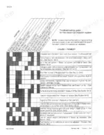
Check main relief and the relief valve for the bucket before blaming the engine, using the pressure checks in the hydraulic troubleshooting section. Then work the pump control solenoid check in the electrical troubleshooting chart on page 278: incorrect amperage at the solenoid points to the controller.
Manual Section: Hydraulic Specifications, Troubleshooting, and Pressure ChecksPilot system dead, joysticks do nothing
Connect a gauge to the quick disconnect fitting between the pilot accumulator and the pilot line filter and read pressure at full throttle. Spec is 570 to 640 psi (3930 to 4413 kPa) as listed on page 428. If it is off, adjust the pilot relief valve; if it will not adjust, the problem is in the pilot relief valve or the pilot pump. The socket head screws that hold the pilot pump to the main pump take 36 pound-feet (49 Nm) on reassembly.
Manual Section: Pilot Pressure Test p. 428Battery charging warning light and low system voltage while the machine is running
Start at the alternator, not the batteries. Probe the white/yellow wire to ground for at least 15 AC volts as the chart on page 285 calls out. Then load test output: it should hold 28 volts at 65 amperes at full throttle. Measure rotor winding resistance at 8 to 9 ohms and replace brushes shorter than 7 mm (0.27 inch).
Manual Section: Electrical Specifications and Troubleshooting p. 285One track crawls slower than the other
Measure track sag and inspect sprocket, idler, and bushing wear using the track troubleshooting procedure. Then follow the travel troubleshooting chart: check the parking brake in the slow side's travel motor, then check that motor for excessive leakage. Drain and refill each final drive with 3.6 U.S. quarts (3.4 litres) of the specified lubricant, and refill idler wheels to 8.2 ounces (250 cc).
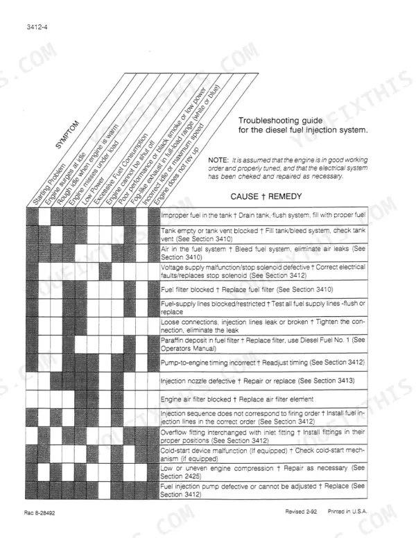
Manual Section: Troubleshooting the Track System p. 357Hard starting, rough idle, and black smoke under load with no power
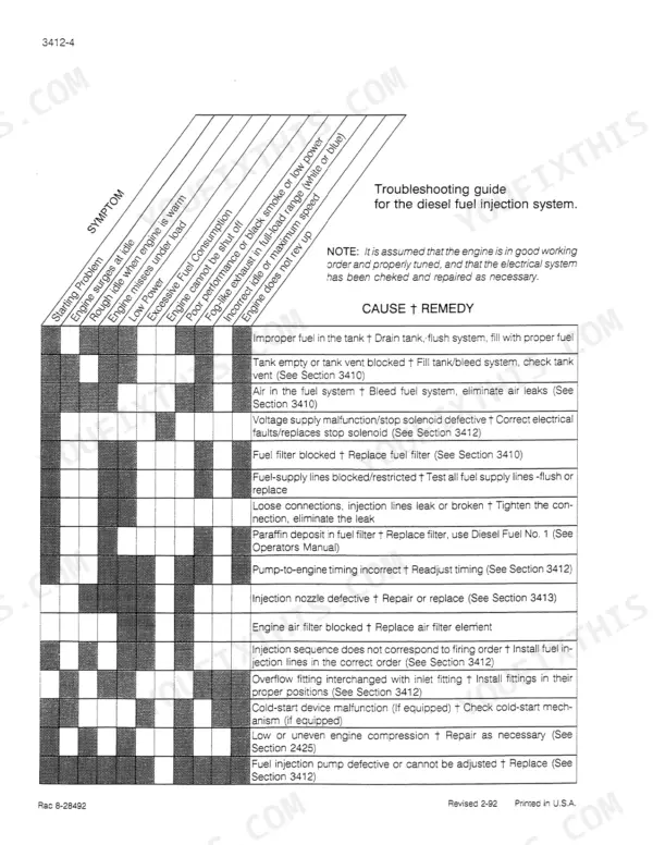
Inspect fuel filters and bleed air from the supply line first, then work the injection troubleshooting steps for surges and low power. Confirm the tank holds clean fuel; capacity is 74 U.S. gallons (280 litres). Pop test injectors before pulling the injection pump.
Manual Section: Fuel Injection System TroubleshootingFrequently Asked Questions
What is the standard torque spec for 1/2 inch Grade 8 bolts on a Case 9040 excavator?
For Grade 8 bolts with a size of 1/2 inch, the standard torque specification is 110-132 pound-feet (149-179 Newton metres). p. 6
What is the engine oil capacity for the 9040 Excavator?
The engine oil capacity for the 9040 Excavator is 21.2 U.S. quarts (20 litres) with a filter change. p. 13
What is the procedure for bleeding air from the cooling system?
To bleed the cooling system, close the radiator drain valve, fill the radiator and coolant reservoir to the fill neck with a 55% ethylene glycol and 45% water mixture, install the radiator cap, and run the engine at high idle until normal operating temperature is reached, then open the heater shutoff valve. p. 27
What is the main bearing bolt torque spec for the 6-830 diesel engine in a Case 9040 excavator?
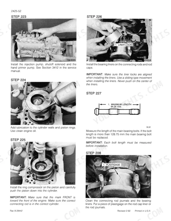
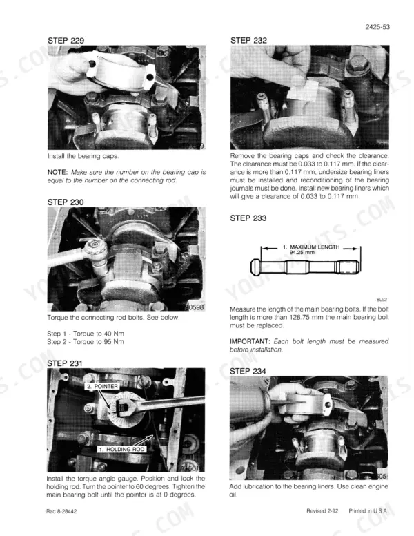
The main bearing bolts on the 6-830 diesel engine should be tightened to 95 Nm plus 60 degrees, with the threads lubricated with engine oil. p. 43
What is the intake valve clearance for the 6-830 diesel engine in a Case 9040 excavator?
The intake valve clearance for the 6-830 diesel engine is 0.30 mm when measured cold. p. 42
Will this Case 9040 Service Manual download right away?
You download the Service Manual yourself: 532 pages, searchable PDF, available immediately. Keep a copy on every device you use.
Is this Case 9040 manual print-friendly?
You can. Print the sections you want for your own use and keep the file as your backup.









Reviews
There are no reviews yet.