


Part of the Case Repair Manuals.
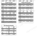
All 220 pages of this Case 40 Crawler Series D Service Manual (OEM #S-406294) target one machine: getting your Series D crawler excavator back to factory condition. Inside you get hydraulic schematics tracing every circuit (track drive, swing, hoist, crowd, tool, and leveler cylinders) plus wiring schematics covering both the 12/24-volt system and the 24-volt system for machines with PIN 6270855 and after. A full troubleshooting section works through mechanical components, electrical faults, and hydraulic system failures, and the Disassembly and Repair chapter takes you through every mechanical, electrical, and hydraulic component in sequence. Set the hydraulic filter center post to 40 lb-ft (54 Nm) maximum; torque the digging brake cover capscrews to 65 lb-ft (88 Nm). Your machine is down and the clock is running. Grab this bookmarked PDF, search any spec by keyword, and get back to wrenching.
What's Inside This Case 40 Crawler Series D Manual
| System | Pages | Key Topics |
|---|---|---|
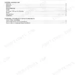
| General | 4-10 | Index, Safety Precautions, Introduction, Nomenclature, Description and Specifications |
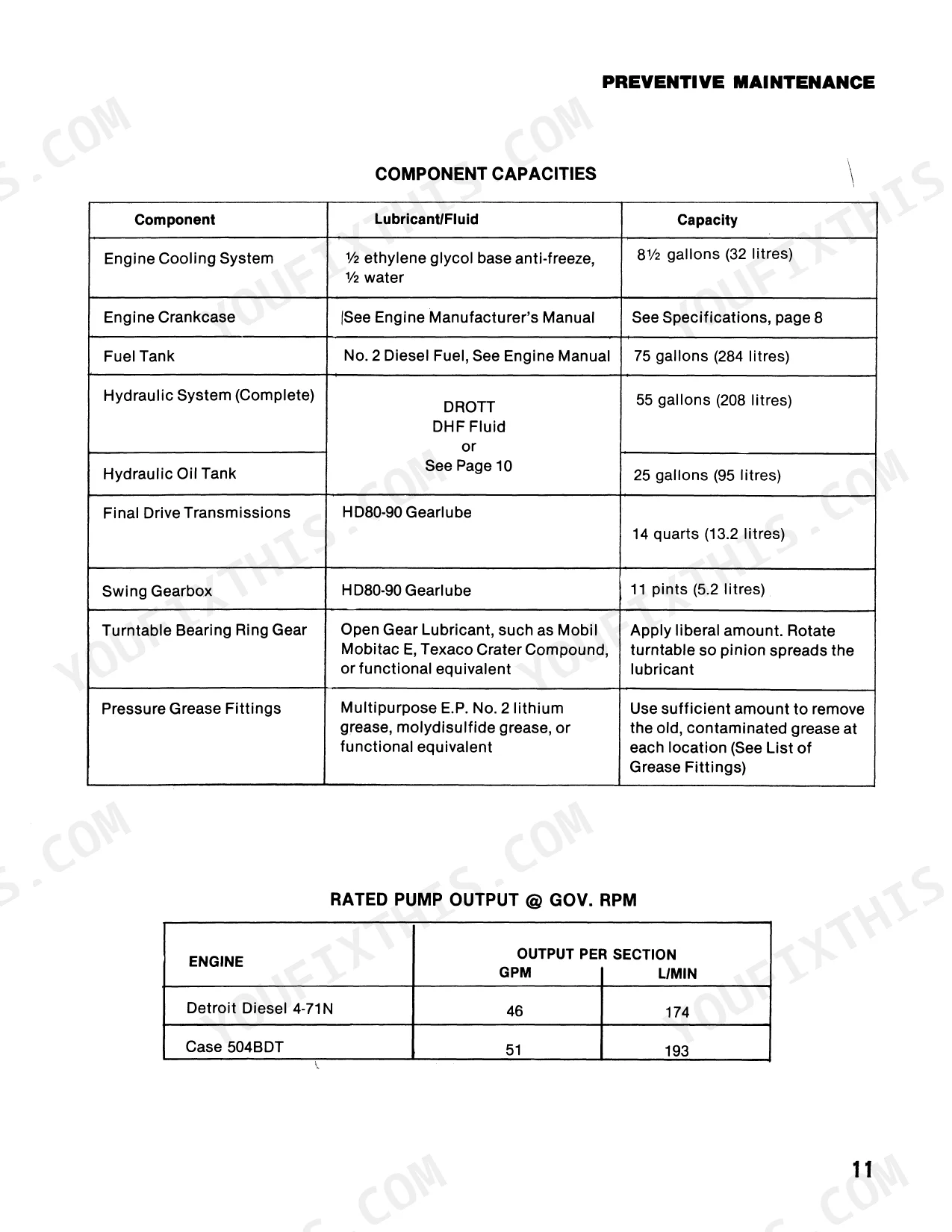
| Preventive Maintenance | 11-23 | Introduction, Hydraulic System Pressures, Component Capacities, Lubricants, And Fluids, Maintenance Chart, Illustrated Listing of Grease Fittings, Itemized Maintenance Instructions |
| Mechanical System | 24-44 | Undercarriage Components, Engine and Related Parts, Turntable Swing, Boom and Attachments, Control Linkages |
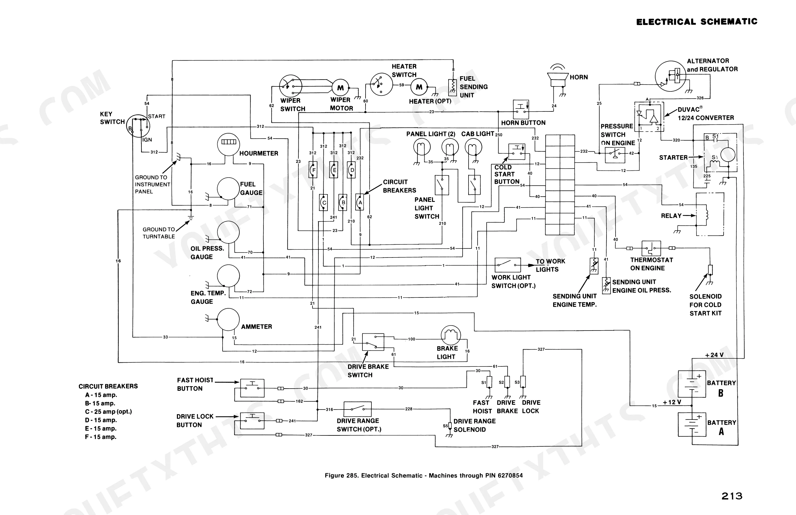
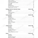
| Electrical System | 45-67 | Introduction, Volt System |
| Hydraulic System | 68-98 | Introduction, System Maintenance, Main Hydraulic System, Track Drive Circuit, Swing Circuit, Hoist Cylinder Circuit, Crowd Cylinder Circuit, Tool Cylinder Circuit |
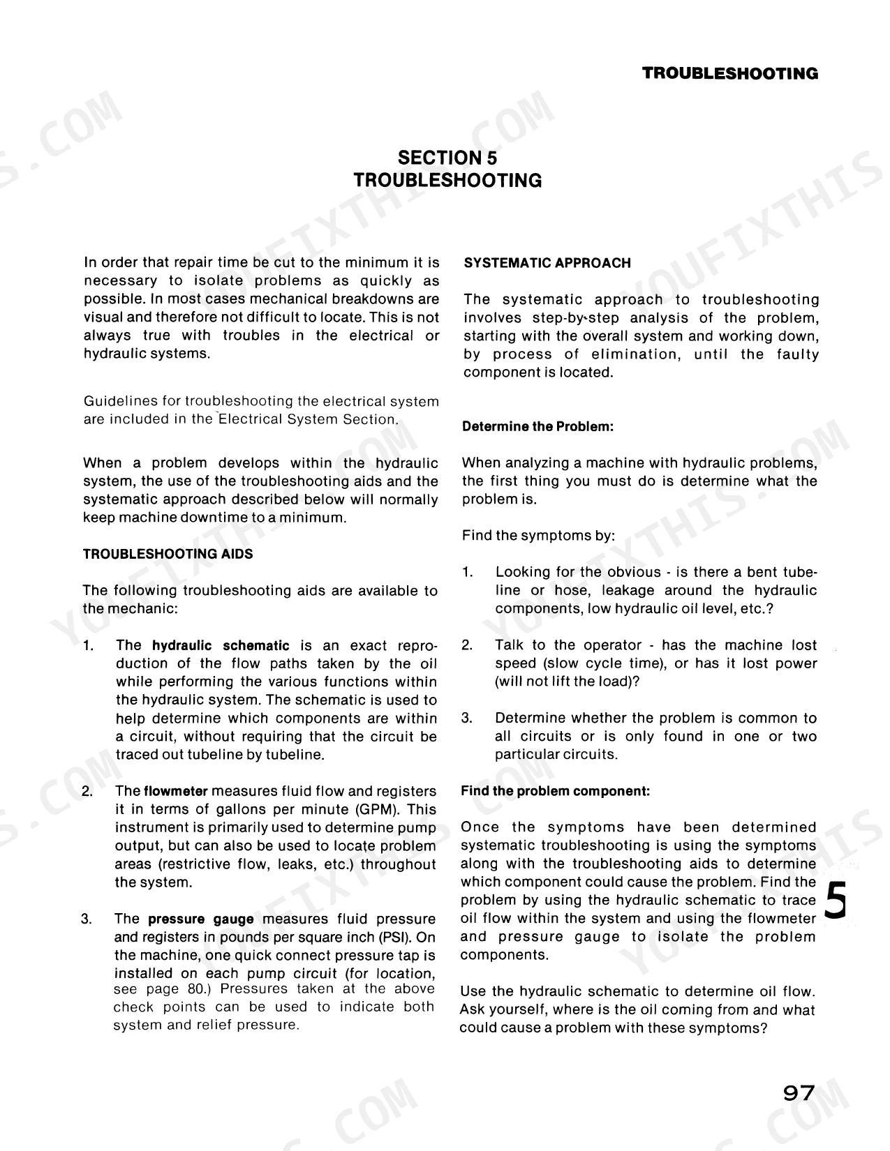
| Troubleshooting | 99-115 | Introduction, Mechanical Components, Volt Electrical System, Hydraulic System and Components |
| Mechanical and Electrical Components | 116-161 | Leveler Assembly, Track Roller, Digging Brake, Final Drive Transmission, Engine and Pump Drive, Swing Gearbox, Boom and Attachments, Wiring Harness Replacement |
| Hydraulic Components | 162-211 | Main Hydraulic Pump, Main Control Valve, Power Sensing Valve, Track Drive Motor, Swing Motor, Hydraulic Cylinders, Hydraulic Oil Tank, Solenoid Control Valve |
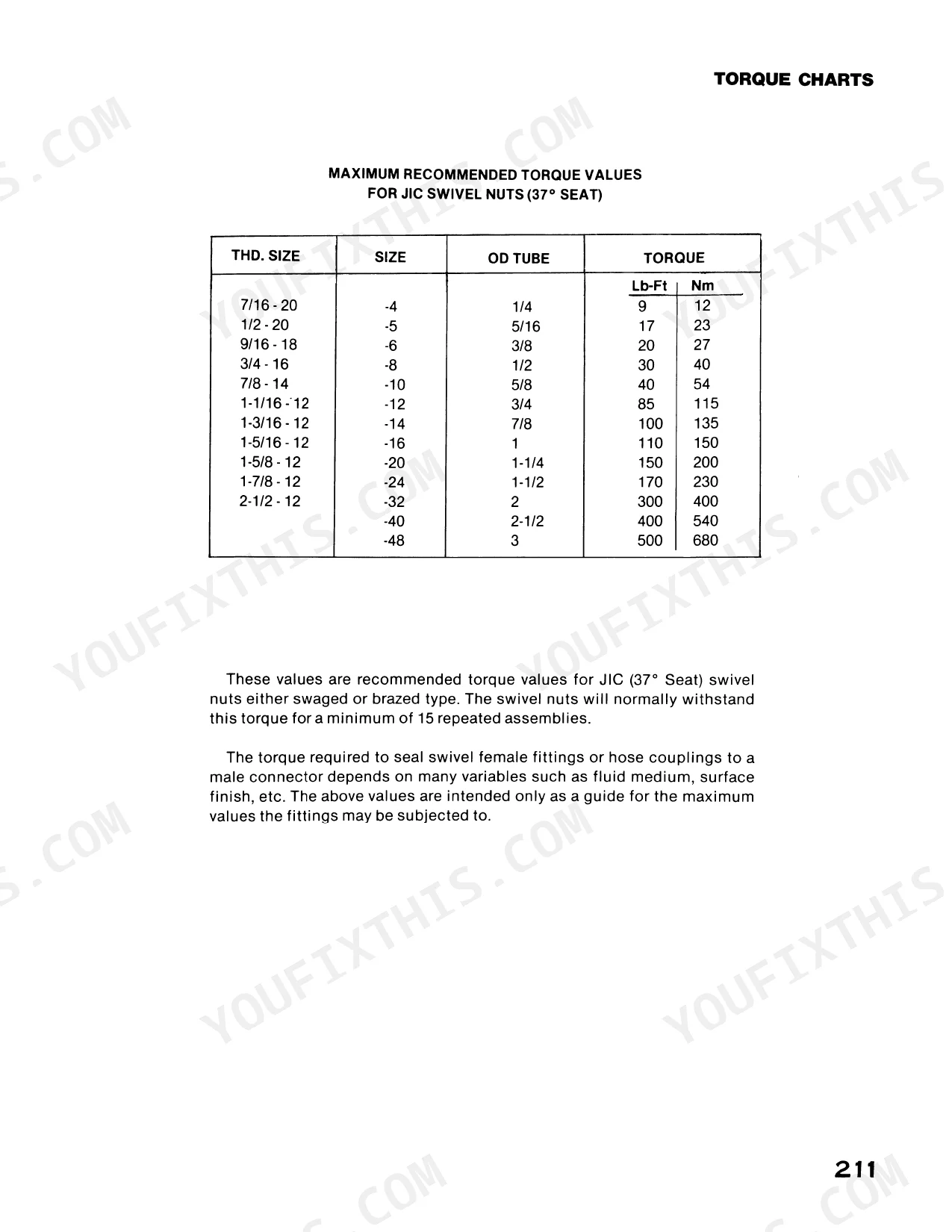
| Torque Charts and Schematics | 212-220 | Torque Charts, Electrical Schematics, Hydraulic Schematic |
Quick Reference Specifications
| Specification | Value | Page |
|---|---|---|
| Track roller bushing bolts torque | 40 lb-ft (54 Nm) | p. 119 |
| Digging brake cover capscrews torque | 65 lb-ft (88 Nm) | p. 123 |
| Starter solenoid voltage drop | .01 volt | p. 61 |
| Hydraulic filter center post torque | 40 lb-ft (54 Nm) maximum | p. 19 |
| Engine Displacement (Case 504BDT) | 504 cu. in. (8 259 cm³) | p. 8 |
| Maximum Torque (Case 504BDT) | 445 lb-ft (603 Nm) @ 1500 rpm | p. 8 |
| Turntable Bearing Capscrew Torque (5/8" Tread Dia., Horizontal Extension Only) | 200 lb-ft (270 Nm) | p. 38 |
Case 40 Crawler Series D Common Problems This Manual Covers
Case 40 Crawler Series D hydraulic system loses pressure after 2000 hours, boom movement slow or stopped
Check the hydraulic filter first. Remove and inspect the filter element; replace if contaminated. Torque the center post to 40 lb-ft (54 Nm) maximum on reinstall. Verify fluid level and condition in the tank. If pressure remains low after filter service, inspect main pump for worn seals and test relief valve pressure settings against spec on page 112.
Manual Section: Main Hydraulic System Troubleshooting p. 105Engine won't crank or cranks slowly, battery connections clean and neutral controls verified
Test the starter solenoid voltage drop: anything above .01 volt on page 61 indicates excessive resistance in the solenoid or cable. Check battery state of charge and load-test both batteries. Inspect the digging brake sensor for continuity; a failed sensor will block the start circuit. Work through the no-crank diagnostic sequence in the electrical troubleshooting charts starting on page 101.
Manual Section: 12/24 Volt Electrical System Troubleshooting p. 101Digging brake won't release or engage, track drive stalls under load
Inspect the brake sensor wiring for chafed insulation or corroded connectors. Remove the brake cover and check the piston for wear or scoring. Reassemble and torque cover capscrews to 65 lb-ft (88 Nm). Verify the brake circuit hydraulic pressure meets spec; cross-reference the track drive troubleshooting chart on page 107 for motor torque and digging brake failure conditions.
Manual Section: Track Drive System Troubleshooting p. 107Track tension inconsistent, especially in cold weather, undercarriage wear accelerating
Adjust track tension at the idler; check roller condition and look for lateral play in idler wheel bearings. When replacing track rollers, press bushing assemblies in, install the shaft, and torque bushing assembly bolts to 40 lb-ft (54 Nm). Inspect sprocket teeth for hooked wear and verify the track brake is releasing fully. Run through the tension adjustment and noisy travel checks on page 100.
Manual Section: Undercarriage Troubleshooting p. 100Swing drifts or chatters when holding position on a grade
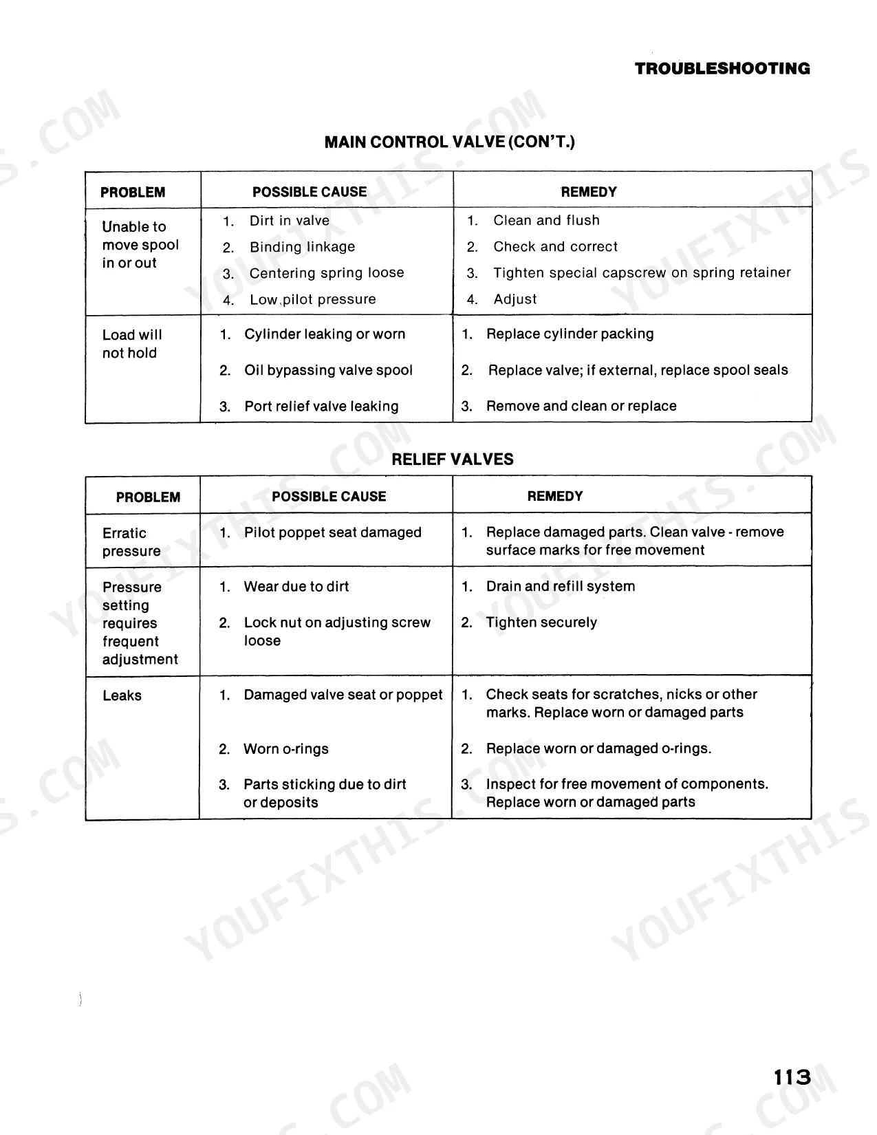
Inspect the swing circuit relief valves for proper seating; an erratic or leaking relief will cause drift under load. Check the main control valve spool for sticking or leaking seals using the procedures on page 111. Verify swing motor case drain flow is within spec. If chatter persists after valve service, inspect swing brake engagement and cross-reference the swing system troubleshooting guide on page 108.
Manual Section: Swing System Troubleshooting p. 108Boom or stick cylinder drifts down slowly when controls released, load drops unexpectedly
Test the cylinder circuit relief valves first; a leaking relief or load-check valve is the most common cause of load drop. Inspect cylinder rod seals for bypass and check for scoring on the rod surface. Verify the main control valve is holding load correctly using the diagnostic steps on page 111. Cross-reference slow or jerky extension symptoms in the cylinder circuits troubleshooting section on page 109.
Manual Section: Cylinder Circuits Troubleshooting p. 109Frequently Asked Questions
Torque specs for final drive
For the final drive transmission, specific torque values are provided for certain components during reassembly. The bearing covers should be torqued to 42 lb-ft (57 Nm), and the brake mounting flange capscrews to 90 lb-ft (122 Nm). Additionally, the cover capscrews should be torqued to 90 lb-ft (120 Nm). p. 126
How quickly can I access this Case 40 Crawler Series D manual after buying?
Instant PDF download (34 MB). You get the full 220-page searchable Service Manual immediately after payment. Open it on your laptop, tablet, or phone right in the shop.
Can I print this Case 40 Crawler Series D manual?
No restrictions at all. Print individual pages, full chapters, or the entire manual. The PDF is completely unlocked.
Are there wiring harness diagrams in this Case 40 Crawler Series D manual?
Included. The Case 40 Crawler Series D Service Manual covers complete wiring harness diagrams, electrical circuits, and connector pinouts.


Reviews
There are no reviews yet.