


Part of the Case Repair Manuals.
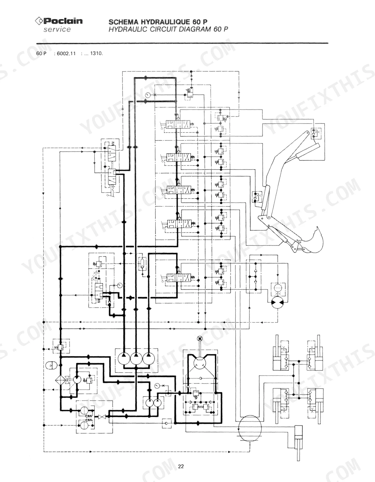
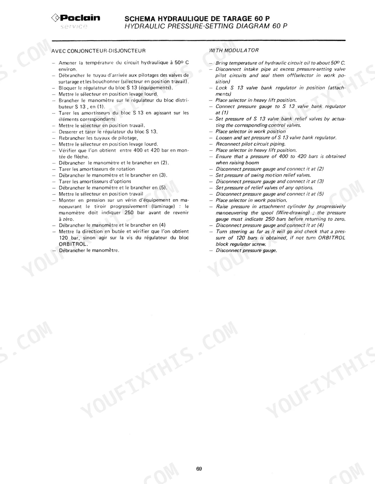
All 184 pages of this Case Drott Poclain Mechanics Handbook (OEM #S406303) are built around one job: keeping the 60P, 60CL, 75P, 75CL, 90P, 90CK, 90CL, 115P, 115CL, 160CK, 220CL, 220CK, 300CK, 400CK, 600CK, and 1000CK hydraulic excavators running. Open it and you get complete hydraulic circuit diagrams for every model in the lineup, high- and low-pressure schematics included, plus a full section of hydraulic pressure-setting data for chasing relief valve faults. Wiring diagrams span every variant from the 60 to the 1000, with electrical connection maps, fuse specs, and battery data, while pneumatic circuit diagrams cover the wheeled models down to tyre inflation pressures and accessories. Set boom raising pressure between 400 and 420 bars on the 60P and 60CL; the larger machines call for 420 to 450 bars. Every hour down costs money. Bookmarked by section and keyword-searchable: open on your tablet, walk to the machine, and get to work.
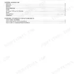
What's Inside This Case Poclain 60–1000 Series Manual
| System | Pages | Key Topics |
|---|---|---|
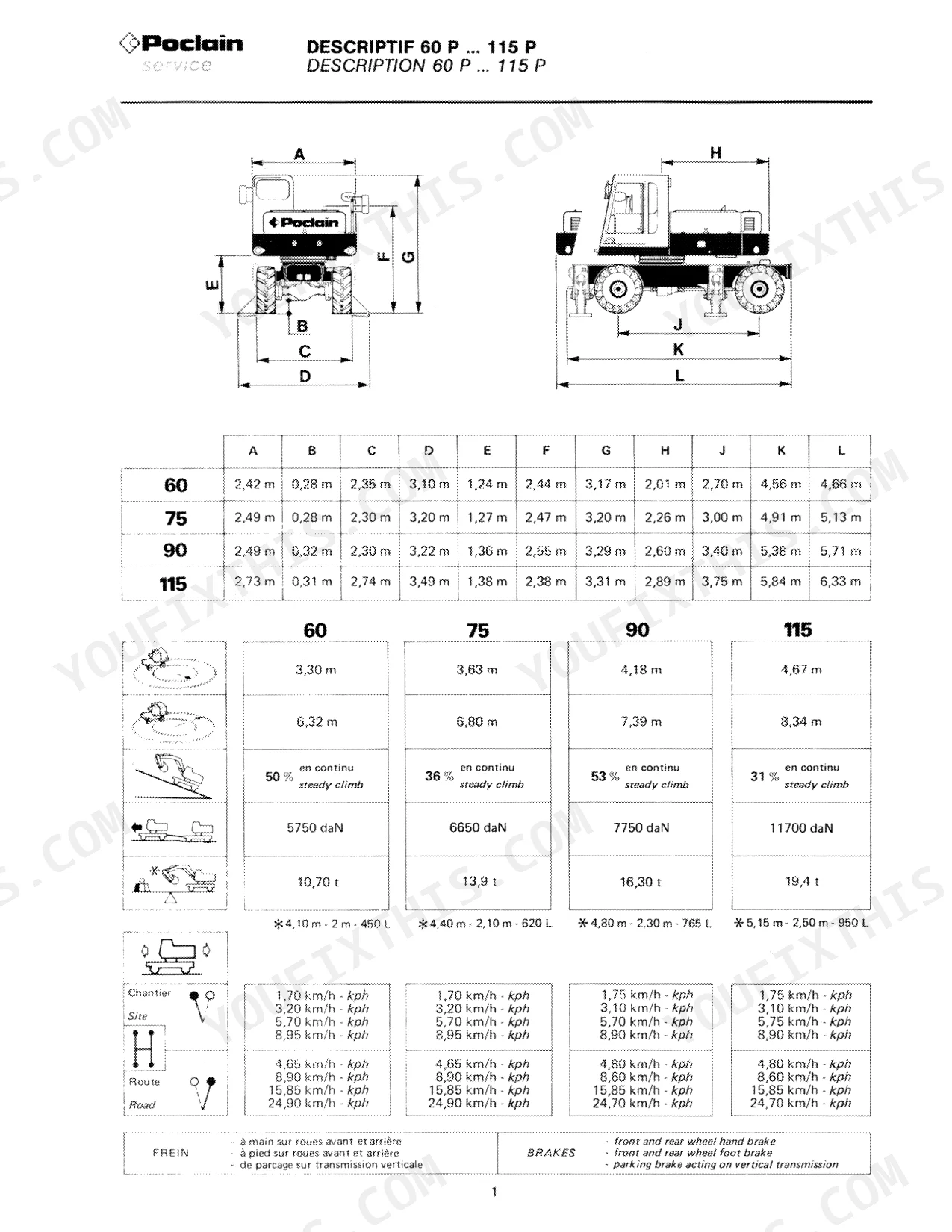
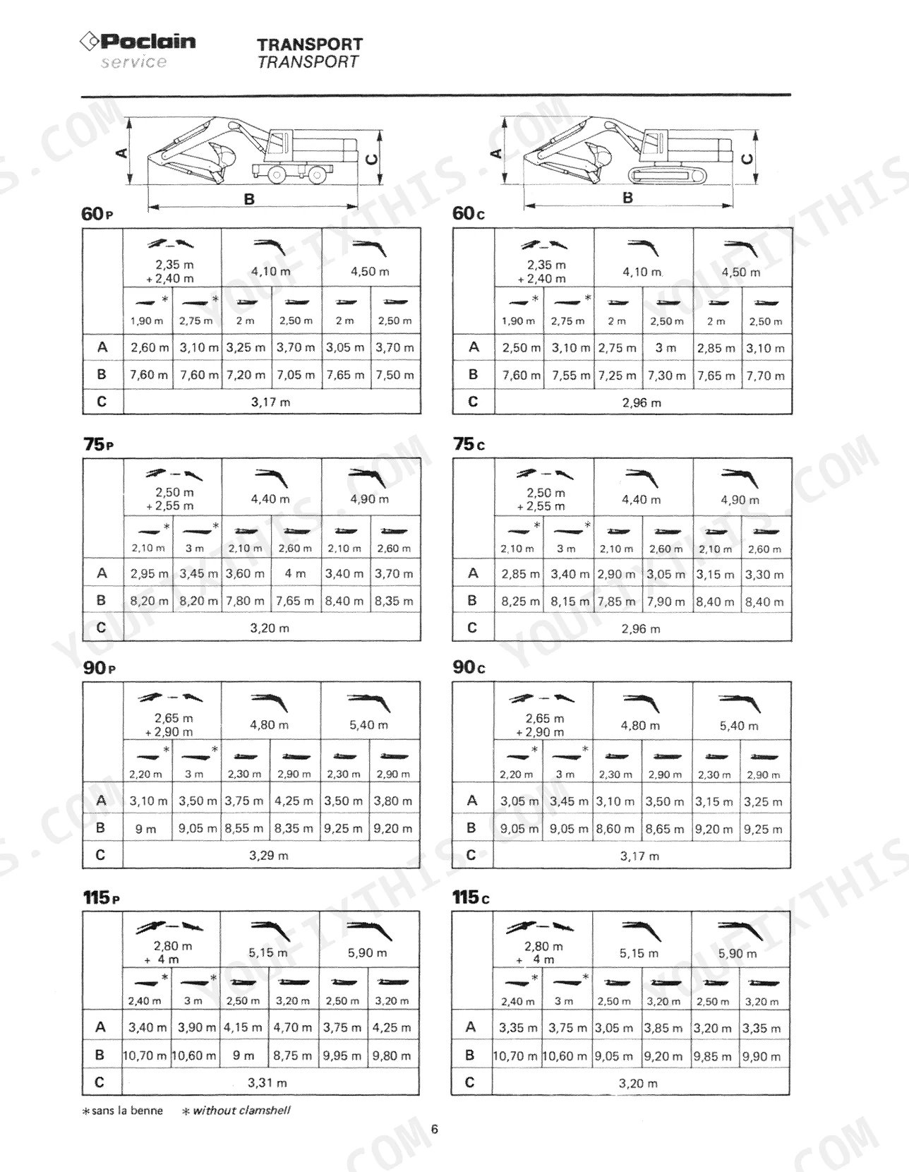
| General | 9-25 | Description 60P... 115P, Description 60C... 160C, Description 220C... 1000C, Characteristics 60... 160, Characteristics 220... 1000, Transport 60... 1000, Handling |
| Centralized Lubrication Circuit | 67-107 | - |
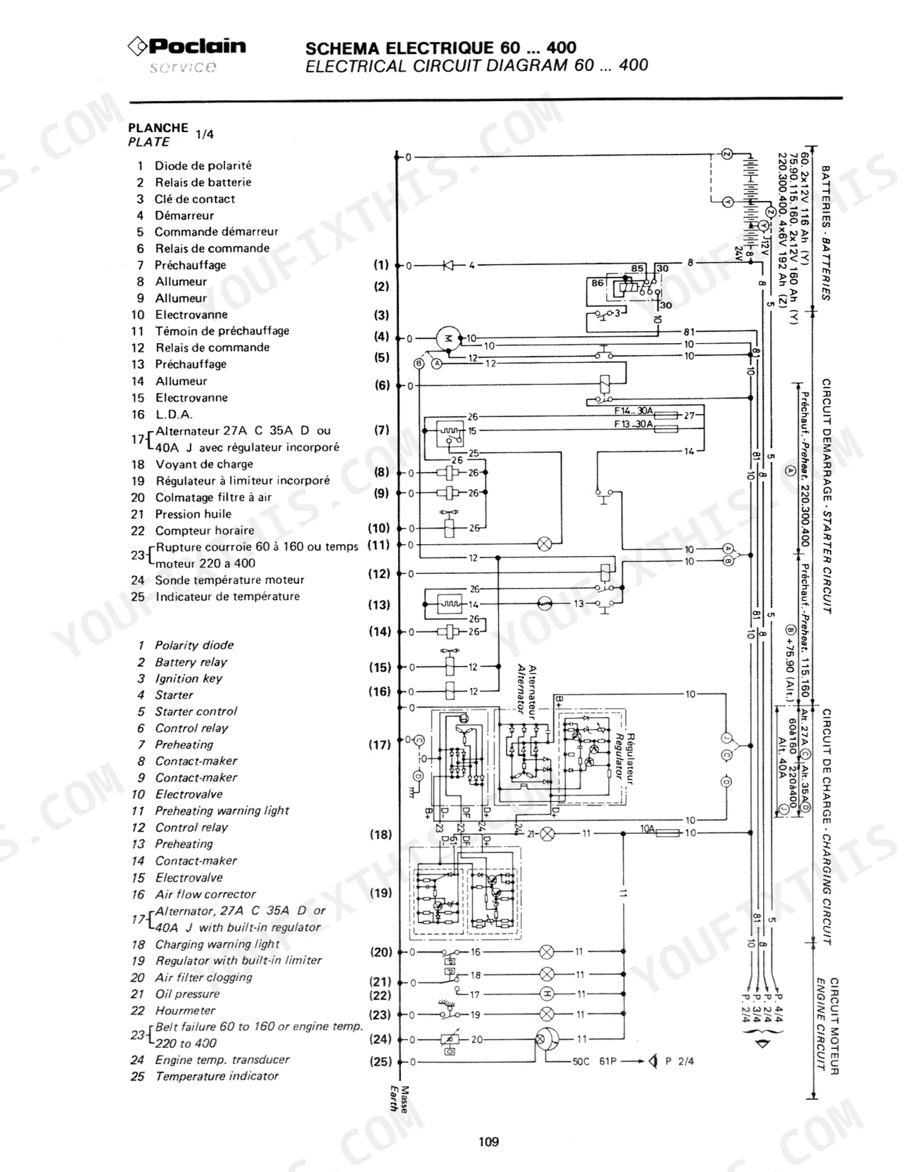
| Electric Circuit Symbols | 108-115 | Unipolar Reverser, Detachable Connection, Ventilator, Bipolar Switch, Accumulator Battery, Fuse |
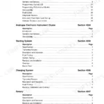
| Electric Circuits | 116-130 | Electric Circuit Symbols, Electrical Circuit Diagrams 60... 400, Electric Circuit Diagramm 600, Electric Circuit Diagram 1000, Electrical Connections, Batteries - Lamps - Fuses |
| Pneumatic Circuits | 131-137 | Pneumatic Circuit Symbols, Pneumatic Circuit Diagrams 60P... 115P, Tyres - Inflating Pressures - Accessories |
| Hydraulic and Mechanical Components | 138-146 | Cylinders, Swing Joints, Hydraulic Motors, High Pressure Pumps, Valave Banks, Engines |
| Various | 147-184 | Pipes and Connections, O-Ring Seals, Plastic Plugs, Hydraulic Hoses, Lugged Pivot Pins, Nuts Hk Hkl - Dowels V - Shim Washers, Bushes, Filters |
Quick Reference Specifications
| Specification | Value | Page |
|---|---|---|
| 60P, 60CL | ||
| Boom raising pressure | 400 to 420 bars | p. 77 |
| 75P, 75CL, 90P, 90CK, 90CL, 115P, 115CL, 160CK, 220CL, 220CK, 300CK, 400CK, 1000CK | ||
| Boom raising pressure | 420 to 450 bars | p. 85 |
| 60P, 60C, 75P, 75C | ||
| Engine Crankcase Capacity | 9 L | p. 21 |
| 90P, 90C, 115P, 115C | ||
| Engine Crankcase Capacity | 12 L | p. 21 |
| 160C, 220C, 300C, 400C, 600C, 1000C | ||
| Engine Crankcase Capacity | 17 L | p. 21 |
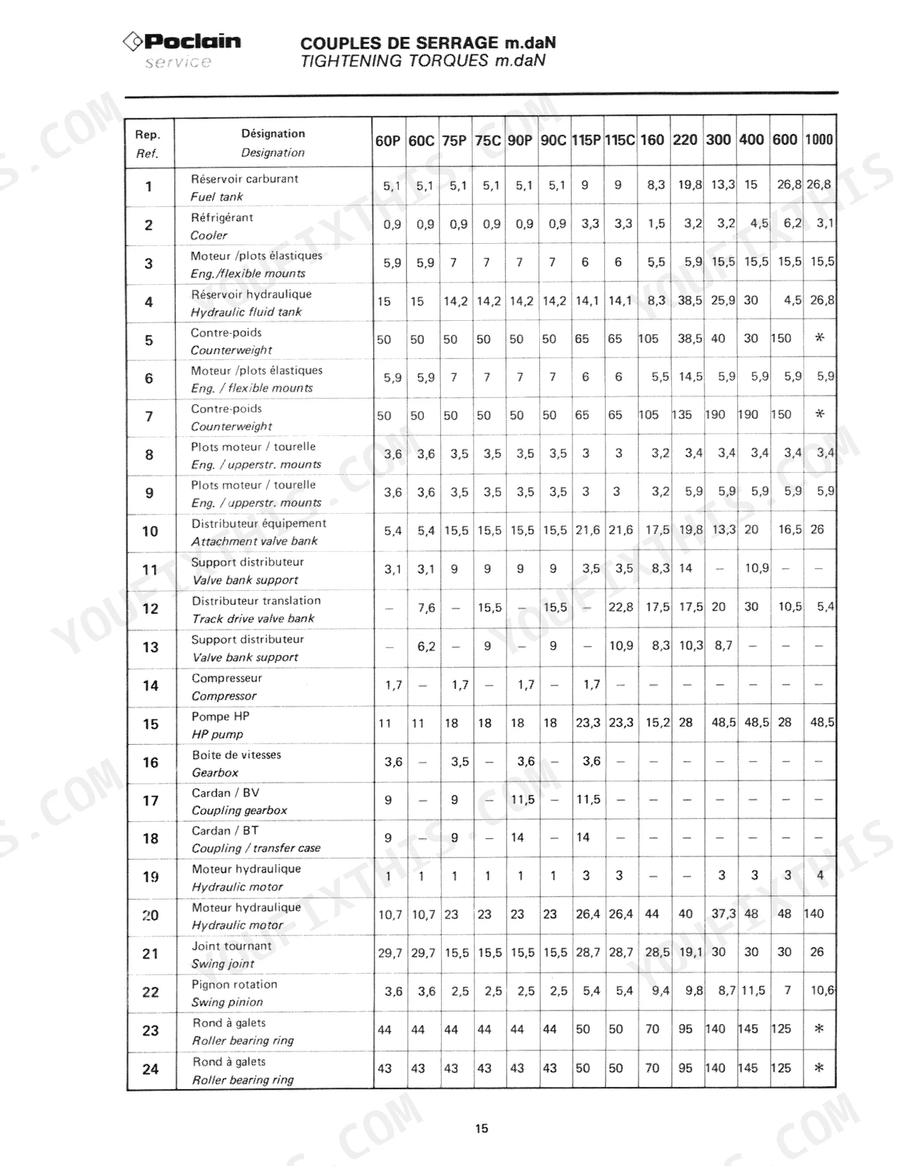
| Fuel Tank Mounting Torque | 9 m.daN | p. 23 |
| 60P, 60C | ||
| Fuel Tank Capacity | 114 L | p. 21 |
| Total Hydraulic Circuit Capacity | 145 L | p. 21 |
| Engine/Flexible Mounts Torque | 5,9 m.daN | p. 23 |
| All Models | ||
| Brake Hydraulic Fluid Tank Capacity | 0,8 L | p. 21 |
| 60P, 60C, 75P, 75C, 90P, 90C, 115P, 115C | ||
| Fuel Tank Mounting Torque | 5,1 m.daN | p. 23 |
Case Poclain 60–1000 Series Common Problems This Manual Covers
Case Poclain hydraulic excavator boom droops or drops under load, won't hold position
Check boom raising pressure against spec — on 75P through 1000CK (except 600CK) target is 420 to 450 bars; on 600CK target is 400 to 420 bars. Connect a calibrated gauge to the high-pressure circuit per the schematic. If pressure reads low, inspect the main relief valve seat for erosion and replace if worn. Verify pump seals before condemning the valve.
Manual Section: Hydraulic Circuit Diagrams p. 85Hydraulic swing or boom movement erratic, drifts or surges without consistent input
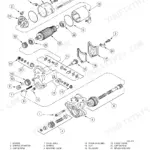
Remove the affected control valve bank and inspect spool bores for scoring and seal wear — internal leakage here causes exactly this symptom. Measure spool-to-bore clearance; any side play beyond manufacturer tolerance means replacement. Refer to the exploded parts view on page 138 for correct spool orientation and seal kit identification before reassembly.
Manual Section: Hydraulic and Mechanical Components p. 138Engine overheating under hydraulic load, temperature gauge climbing into red
Check the hydraulic oil cooler core for blockage — compressed air or low-pressure water flush from the fin side, not the oil side. Verify total hydraulic circuit capacity is correct for your model (145 L on 60P and 60CL per page 21 specs) and that no aeration is present. If oil looks milky or smells burnt, drain fully, flush, and refill to spec before returning to service.
Manual Section: Hydraulic Pressure-Setting Diagrams p. 21Electrical system intermittent faults, warning lights flicker or solenoids drop out randomly
Pull the electrical diagram for your model range — pages 117 through 124 cover models 60 through 400, pages 125 to 126 cover 600 and 1000. Check battery terminals and ground straps first; verify fuse ratings match the values listed under Batteries-Lamps-Fuses. Test solenoid coil resistance at each valve bank — an open or shorted coil reads outside spec and pulls the whole circuit down.
Manual Section: Electric Circuits p. 117Undercarriage or swing joint leaking hydraulic oil, wet around pivot area
Inspect swing joint seals using the component breakdown on page 138. Wipe the area clean and cycle the machine slowly to locate the exact leak path before pulling anything apart. Check hydraulic hose connections at the joint for fretting or loose fittings — refer to the hose and connection specifications starting on page 147. Replace O-ring seals to the correct size per the O-Ring Seals section; never reuse compressed or cut rings.
Manual Section: Hydraulic and Mechanical Components p. 138Centralized lubrication system not delivering grease, dry pivot pins or boom joints
Verify the lubrication pump is cycling by watching the indicator during engine-on operation. Trace the distribution lines from the pump manifold — a single blocked line starves all points downstream of it. Inspect each luged pivot pin for adequate grease purging at the relief point; if no purge is visible, the line is blocked or the fitting is seized. Service procedures and circuit layout begin on page 77.
Manual Section: Centralized Lubrication Circuit p. 77Frequently Asked Questions
What are the recommended service intervals?
The manual provides a table of service intervals for various components. For instance, the fuel tank, hydraulic fluid tank, and total hydraulic circuit have a 10-hour interval for checking the level. Other components like the engine crankcase, gearbox, and axles have longer intervals, such as 100 hours for the engine crankcase and 2000 hours for the gearbox and axles. p. 21
What fluids and capacities does this machine require?
The machine requires specific lubricants, including POCLAIN HYDRAULIC FLUID (25 kg drum, part J 00 032 - 28), ELF PERFORMANCE engine oil (SAE 30 or 20W/20), ELF FREELUB HDS brake fluid (2 L drum, part X 00 032 - 41), TRANSELF EP. 80 W 90 EP oil, POCLAIN GREASE EP general purpose grease, and POCLAIN GEAR MS 2 fluid grease. Capacities vary by model; for example, a 60P model has a 9 L fuel tank, 114 L hydraulic tank, and 10.4 L total hydraulic circuit capacity. p. 20
What are the hydraulic system specifications?
Hydraulic system specifications vary by model. For example, the 60-160 series excavators use 4 to 6 hydraulic pumps, with engine speeds of 2150-2300 tr/mn. The hydraulic tank capacity ranges from 114 L to 410 L, and the total hydraulic circuit capacity from 10.4 L to 25.4 L. Pressure settings for various functions, such as 'Travail/Work' and 'Levage lourd/Heavy lift', can be regulated to specific bar values, like 320 bar for the main regulator. p. 101
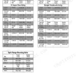
What torque specifications are listed?
The manual lists various torque specifications in m.daN. For swing gear bolts, tightening is done in two phases, for example, bolts 1 and 2 at 90°. Engine components have specific torques, such as head assembly bolts at (1) 45 + 45 + 45 m.daN and connecting-rod head bolts at (1) 60 + 30 m.daN. Unions and connections also have torque values, with a 13 mm union for high pressure requiring 3 m.daN. p. 22
Is this Case 60P & variants Mechanics Handbook a digital download?
A 184-page Mechanics Handbook in searchable PDF format, available the moment you complete checkout. View on computer, tablet, or phone, with no shipping wait.
Are there any print restrictions on this manual?
Yes. The PDF has no DRM restrictions, so print any page or section you need for your shop. Works with any standard printer.
Does this Case 60P & variants manual include hydraulic schematics?
Included. A hydraulic system diagram shows the main hydraulic layout for the Case 60P & variants.


Reviews
There are no reviews yet.