


Part of the Case Repair Manuals.
This 938-page Case MX Series Service Manual (OEM Rac 7-87830) is the Case mx100 service manual pdf covering MX12 through MX270, from controller calibration down to the hitch valve castings. You get complete wiring schematics with pinout charts, hydraulic plumbing layouts for the PFC axial piston pump, and a full transmission troubleshooting section covering the powershift clutch pack and MFD control logic. Open to the fault code retrieval procedures and you'll find the exact reset sequence: press and hold both INCR and DECR keys for 10 seconds. Steering relief valve set pressure runs 2750 PSI (190 bar), with the adjustment lock nut torqued to 30-35 lb ft (41-50 Nm). No more chasing hitch or PTO fault codes with a multimeter and a guess. Bookmarked by system, so you jump straight to transmission, brakes, or hitch controls and start wrenching.
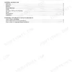
What's Inside This Case MX12–MX270 Series Manual
| System | Pages | Key Topics |
|---|---|---|
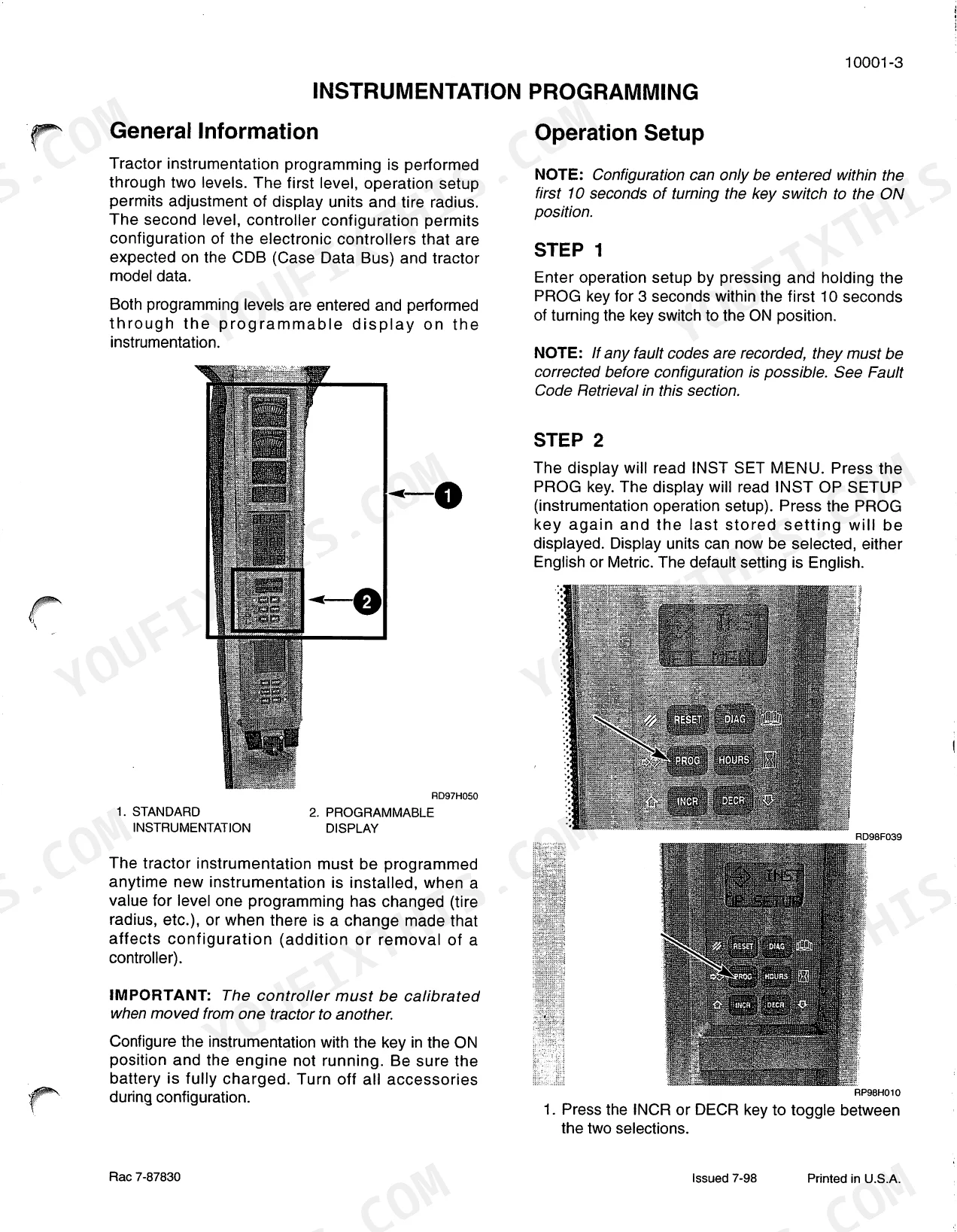
| Instrumentation Programming & Fault Codes | 1-49 | Operation Setup, Controller Configuration, Configuration/Calibration Mode |
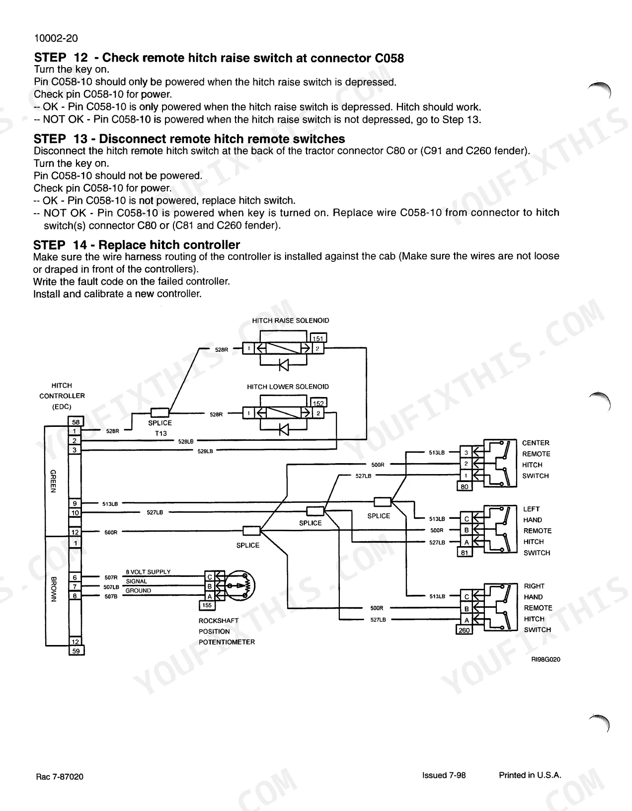
| Hitch Controller Calibration & Fault Codes | 50-160 | Setup Process, Hitch Calibration Menu, Hitch Setting Menu, Hitch View Menu, Hitch Failure Modes, Performance Fault Codes |
| Transmission Controller Calibration & Fault Codes | 161-368 | Trans View Mode, Trans Setup Mode, Pedal Calibration, Valve Calibration, Load Defaults, Transmission System Components |
| Armrest Controller Calibtation & Fault Codes | 369-431 | Armrest Main Menu, Hitch Menu, Throttle Menu, Remote Valve Menu, MFD Menu, Transmission Menu |
| Remote Hydraulics Controller Fault Codes | 432-525 | Aux 1 Lever Potentiometer, Aux 2 Lever Potentiometer, Aux 3 Lever Potentiometer, Aux 4 Lever Potentiometer, Aux 5 Lever Potentiometer, Timer Potentiometer |
| Oto Controller Configuration & Fault Codes | 526-605 | PTO Main Menu, PTO Speed Menu, Brake Lamp Menu, PTO Solenoid, Diff Lock Solenoid, PTO Clutch |
| Performance Monitor Controller Fault Codes | 606-620 | Controller Memory, Software Execution, Case Data Bus, Instrumentation Controller, Engine Controller, Hitch Controller |
| Automatic Temperature Control Fault Codes | 621-630 | High Pressure Switch, Low Pressure Switch, Blower Potentiometer, Temperature Control Potentiometer, Mode Door Control Potentiometer, Freeze Sensor Thermistor |
| Safety, General information/maintenance Schedule | 631-694 | Cleaning, Inspection, Bearings, Gears, Oil Seals, O-Rings and Gaskets, Shafts |
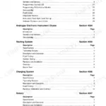
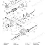
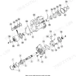
| Powershift Transmission System How It Works & Troubleshooting | 695-754 | Transmission System Controls, Transmission System Components, Mx Magnum Powershift Transmission Clutch Layout, Powershift Valve Clutch Engagements, Inching Valve Operation |
| Mechanical Front Drive MFD Control System, How It Works | 755-773 | MFD, Electronic MFD Control, MFD Control Modes, MFD Functional Tests, MFD Valve, MFD Clutch Disengaged |
| Differential Lock Control System How It Works | 774-789 | Differential Lock, Electronic Differential Lock Control, Differential Lock Control Modes, Differential Lock Functional Tests, Differential Lock Valve |
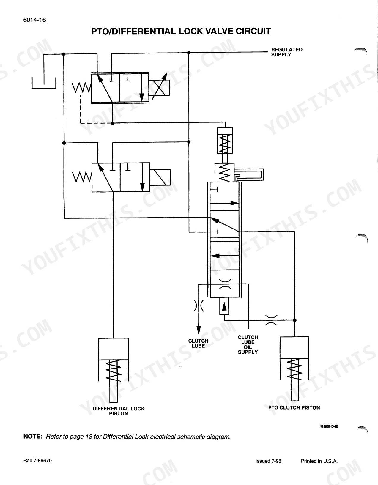
| PTO Control System How It Works | 790-815 | Power Take Off, Electronic PTO Control, PTO Control Modes, PTO Valve Oil Supply, PTO Proportional Current Control Solenoid Cartridge Valve, PTO Clutch Disengaged |
| Brake System How It Works & Troubleshooting | 816-831 | General Information, Hydraulic Brake Control, Brake Valve Switches, Brake Wheel Cylinders, Problem - Brake(s) Will Not Disengage (Drag) |
| Hydraulic System How It Works with Troubleshooting | 832-915 | General Introduction, Pump and Filter Plumbing Layout, Regulated Supply System Tube Layout, Steering and Brake Tube Layout, Pfc Axial Piston Pump, Priority and Regulator Valve |
| Hitch System How It Works | 916-938 | Three Point Hitch, Electronic Hitch Control, Ehc System Features, Hitch Control Valve, Raise and Lower Solenoids, Load Check Ball |
Quick Reference Specifications
| Specification | Value | Page |
|---|---|---|
| Fault Code Clearing Procedure | Press and hold both the INCR and DECR keys for 10 seconds | p. 10 |
| Standard Flow Pump Replacement Flow Rate | below 21.6 GPM (81.8 L/min) | p. 852 |
| Transmission Clutch Pack Fill Time | 180 to 300 milliseconds | p. 743 |
| Steering Relief Valve Set Pressure | 2750 PSI (190 bar) | p. 853 |
| Steering Relief Valve Adjustment Lock Nut Torque | 30 to 35 lb ft (41 to 50 Nm) | p. 854 |
| PFC Pump High Pressure Standby Specification | 2800 PSI (193 bar) to 3000 PSI (207 bar) | p. 867 |
| Hitch Solenoid Resistance | 6.9 ohms at 25 C | p. 62 |
| Transmission Regulated Pressure | 1930 to 2034 kPa (280 to 300 PSI) at 1500 engine RPM | p. 191 |
| Battery Voltage Minimum | 12.8 volts | p. 211 |
| Inching Pedal Potentiometer Resistance | 3.7 - 4.4 k ohms | p. 220 |
| Master Clutch Solenoid Resistance | 6.2 - 6.7 ohms at 25°C (77°F) | p. 308 |
| Hitch Position Potentiometer Size | 1K ohms ± 10% | p. 391 |
Case MX12–MX270 Series Common Problems This Manual Covers
Case MX120 hydraulic power loss during heavy lifting, pump loses pressure after 30 minutes of operation
Test the PFC pump high pressure standby setting; it should read 2800 to 3000 PSI (193 to 207 bar) per page 867. If pressure fades after warm up, flow-test the pump and replace it once output drops below 21.6 GPM (81.8 L/min), the replacement threshold listed on page 852.
Manual Section: Hydraulic System How It Works with Troubleshooting p. 867Transmission slipping or won't hold gears under load, especially in wet field conditions
Check transmission regulated pressure at the test port; it must read 1930 to 2034 kPa (280 to 300 PSI) at 1500 engine RPM per page 191. Low pressure points to clutch pack wear or a seal leak. Verify clutch pack fill time stays within 180 to 300 milliseconds, the spec listed on page 743; a slower fill means a worn solenoid.
Manual Section: Transmission Controller Calibration & Fault Codes p. 191Engine shuts down intermittently at low RPM with no fault codes stored, even after fuel filter service
Clear stored codes using the procedure on page 10 (hold INCR and DECR for 10 seconds), then watch for a new ECU-01 fault. Check battery voltage under load; it must stay above 12.8 volts per page 211, since low voltage causes intermittent ECU dropout that mimics fuel starvation. Inspect harness connectors for corrosion.
Manual Section: Instrumentation Programming & Fault Codes p. 10PTO won't engage or modulates erratically under load with no stored fault codes present
Disconnect the PTO solenoid and measure resistance across the terminals; it should read 6.0 to 6.8 ohms at 25 C (70 F) per page 539. A reading outside that range means a bad coil, replace the solenoid. If resistance checks good, verify the solenoid harness connector is seated and free of corrosion before testing PTO clutch engagement again.
Manual Section: Oto Controller Configuration & Fault Codes p. 539Three-point hitch won't capture position or raises and lowers on its own with no codes
Measure the hitch solenoid coil resistance; it should read 6.9 ohms at 25 C per page 62. Also check the hitch position potentiometer, rated at 1K ohms plus or minus 10 percent per page 391; drift outside that tolerance causes the hitch to drift or fail to hold a set position. Replace whichever component falls outside spec.
Manual Section: Hitch Controller Calibration & Fault Codes p. 62Steering feels heavy, hard to turn, or wanders at low engine RPM
Test steering relief pressure; it should hold at 2750 PSI (190 bar) per page 853. If pressure reads low, adjust the relief valve lock nut, torqued to 30 to 35 lb ft (41 to 50 Nm) as specified on page 854, then retest. Persistent low pressure after adjustment points to a worn pump or relief valve requiring replacement.
Manual Section: Hydraulic System How It Works with Troubleshooting p. 853Frequently Asked Questions
How to reset error codes on Case MX100/MX110/MX120/MX135?
To reset error codes on Case MX series tractors, navigate to the fault code retrieval menu for the specific controller (e.g., Instrumentation, Hitch, Transmission, Armrest, Remote Hydraulics, PTO, Performance Monitor) and press and hold both the INCR and DECR keys for 10 seconds. This action will erase all fault codes for that specific controller. p. 10
How to reset the transmission oil pressure warning on Case MAXXUM MX series?
To reset a transmission oil pressure warning, first correct the underlying fault. Then, depress the "Reset" button on the programmable display to clear the fault. For specific fault codes like TRANS 5011 (low hydraulic pressure), the corrective action starts with clearing all fault codes. p. 698
How to reset the hydraulic system fault on Case MX135?
To reset a hydraulic system fault, address the root cause of the hydraulic system fault. After the problem is corrected, access the fault code retrieval menu for the relevant hydraulic controller and press and hold both the INCR and DECR keys for 10 seconds to clear the fault codes. p. 435
What are the replacement specifications for Hydraulic pump (MX Maxxum series)?
The front regulated pump should be replaced if its flow is below 21.6 GPM (81.8 L/min). The charge/lubrication pump has a flow rate of 39 US GPM (148 L/min), and the steering/regulated circuit pump has a flow rate of 27 US GPM (102 L/min) at rated engine speed (2000 RPM). p. 835
What are the replacement specifications for Fuel filter (MX engine series)?
For Case MX engine series, the engine primary fuel filter should have its water drained every 50 hours. The main engine fuel filters should be changed every 600 hours. p. 636
How will I receive this Case MX12, MX30, MX100, MX110, MX120, MX135, MX150?
This is a 938-page searchable PDF (103 MB) ready for immediate download. Works on any device, so pull it up on your phone while you're under the hood. No shipping, no waiting.
Can I print this Case MX12, MX30, MX100, MX110, MX120, MX135, MX150, MX170?
No restrictions at all. Print individual pages, full chapters, or the entire manual. The PDF is completely unlocked.


Reviews
There are no reviews yet.