


Part of the Case Repair Manuals.
All 392 pages of this Case 930 Comfort King Service Manual PDF (OEM #9-74911) cover the complete 730, 830, 930, and 1030 Series tractors: diesel and LP gas engines, six-speed spur gear transmission, PTO clutch, Draft-O-Matic hydraulics, and power steering. You get full wiring diagrams for charging, cranking, and ignition circuits, plus hydraulic schematics tracing oil flow through the control valve and power steering system. Open to a complete fuel injection section covering Powrcel service, Robert Bosch PES pump timing procedures, and separate cylinder head rebuilds for both diesel and LP gas variants. Set your Grade 5, 5/16-inch manifold capscrews to 15-18 ft-lbs; plan your power steering filter swap at 1,000 hours. No more guessing which procedure applies to your model. Grab it on your tablet and walk straight to the machine.
What's Inside This Case 930 Comfort King Manual
| System | Pages | Key Topics |
|---|---|---|
| Instructions for Removal and Installation of the Factory Installed Operators Cab | 5-12 | Removal, Installation, Wiring, Fuel Tank Mounting, Firewall Filler Plates, U-Bolts |
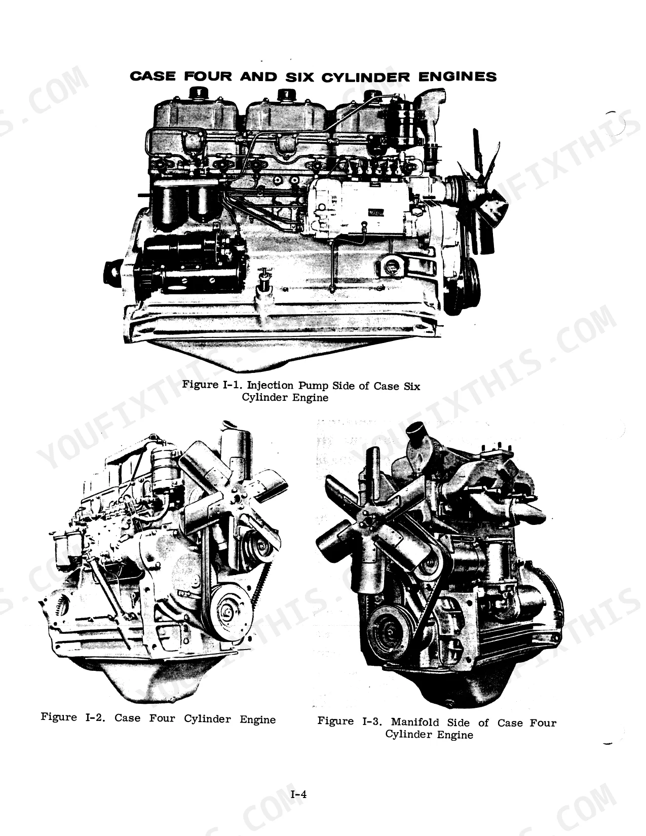
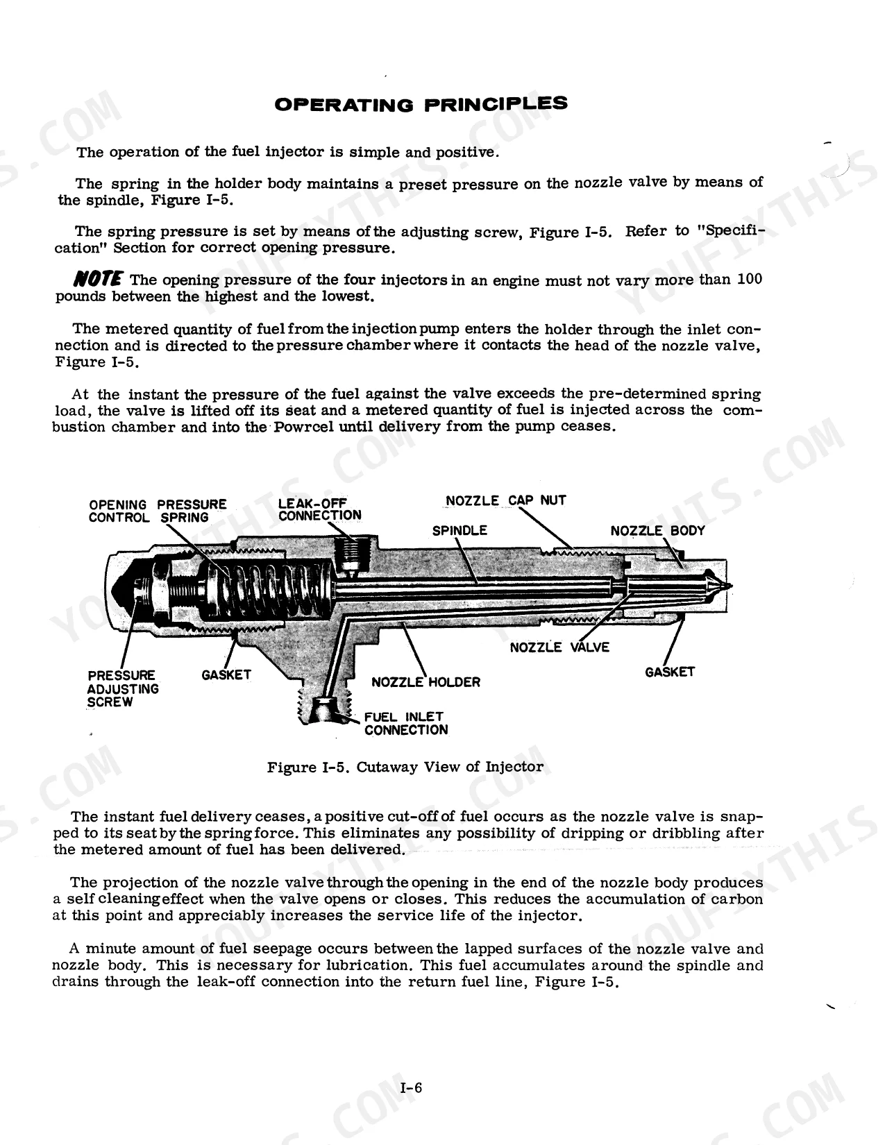
| Servicing the Fuel Injectors Case Powrcel Fuel Injection Pump | 13-56 | Description and Operating Principles, Diesel Tool Kits, Checking Injector Operation on the Engine, Removing and Installing Injector, Nozzle Test Stand, Test Stand Installation |
| Installation Instructions for A57827 Heater Kit on the 930 & 1030 Series Tractor | 57-59 | Knockout Plugs, Mounting Bracket, Heater Hose, Shut-Off Valve, Heater Switch, Light Panel Retaining Screw |
| Section C: Specification for Case a 401 Diesel and Case Lp Gas Engines | 60 | Engine Specifications, Connecting Rods, Piston and Pin, Crankshaft and Main Bearings, Valves, Tightening Torque Specifications |
| Group I: Specifications | 61-70 | General Specifications, Electrical Specifications, Engine Wear Limits, Torque Specifications |
| Section F: Electrical System, the Charging and Cranking Circuits, Ignition Syst | 71-101 | Battery Service, Regulator Specifications, Generator Output, Cranking Motor Specifications, Ignition System Distributors, Wiring Diagrams |
| Section K: Servicing the Cylinder Heads, Valve Systems, Rocker Arms, Decompress | 102 | Cylinder Head Removal, Decompressor Inspection, Rocker Arm Disassembly, Valve System Servicing, Valve Seat Grinding, Tappet Clearance Adjustment |
| Group Ii: Engine | 103-120 | Cylinder Heads, Valve Systems, Rocker Arms, Engine Block Assemblies, Spark Ignition Governor, Fuel Injection Pump |
| Section L: Servicing the Cylinder Heads, Valve Systems, and Rocker Arms on Cas | 121-136 | Cylinder Head Removal, Rocker Arm Disassembly, Valve System Inspection, Valve Refacing, Valve Seat Grinding, Tappet Clearance Adjustment |
| Section M: Servicing the Assemblies Contained in the Engine Block | 137-182 | Engine Lubricating System, Pistons, Connecting Rods, Cylinder Sleeves, Crankshaft, Main Bearings, Flywheel, Camshaft |
| Section M : Supplement No. 1 Servicing the Spark Ignition Governor | 183-196 | Governor and Throttle Linkage, Governed Engine Speed, Adjusting Governed Engine Speed, Checking Governor Action, Checking Governor Linkage, Servicing Governor |
| Section N: Servicing the Lp Gas Model "R" Regulator and KG1 Carburetor | 197-204 | Introduction, Disassembly-Inspection-Assembly of the Regulator, Disassembly-Inspection-Assembly of the Carburetor, Adjustments |
| Group Iii: Fuel Syatem | 205-206 | Diesel Fuel Injection Pump, Lp Gas Regulator, Carburetor |
| Group Iv: Hydraulic System | 207-208 | Hydraulic Cylinders, Hydraulic Pump, Control Valve |
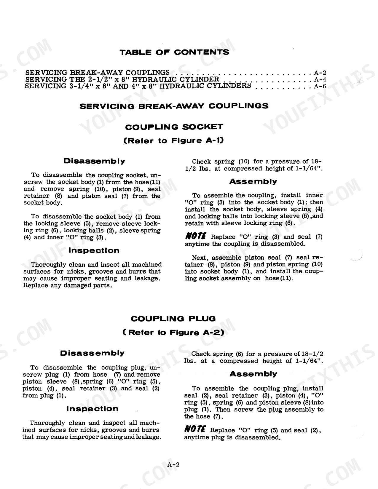
| Section a: Servicing Break-Away Couplings and Portable Hydraulic Cylinders | 209-216 | Servicing Break-Away Couplings, Servicing 2-1/2" X 8" Hydraulic Cylinder, Servicing 3-1/4" X 8" and 4" X 8" Hydraulic Cylinders |
| Section D: Servicing the Hydraulic Control System on Case Wheel Tractors | 217-240 | Oil Flow, Hydraulic Valve and Pump, Hydraulic System Filter, Disassembly and Inspection of Pump, Disassembly of Control Valve, Checking Hydraulic Pressure |
| Section R: Supplement No. 2 Draft-O-Matic Adjustments and Check-Out Procedure O | 241-258 | Draft-O-Matic Check-Out Procedure, Hydraulic System Pressure Checks, Draft-O-Matic Test Fixture Specifications, Tire Pressure, Hitch Height, Sensing Spring Preload |
| Group V: Steering System | 259-260 | Front Wheel Bearings and Seals, Front Axles, Steering Gear, Combined Power Steering Cylinder and Valve, Drag Link and Toe-In Adjustment, Bleeding the Steering System |
| Section O: Serviving the Steering System on Case Wheel Tractors | 261-288 | - |
| Section P: Servicing the Gear and Roll Type Power Steering Pumps on Case Wheel | 289-316 | Power Steering Pump Operation, Oil Flow, Relief Valve Pressure Check, Gear Type Steering Pump, Roll Type Steering Pump, Filling and Bleeding the Power Steering System |
| Section S: Servicing the Six-Speed, Spur Gear Transmission, Final Drive and Dif | 317-362 | Transmission Top Cover and Gear Shift, Gear Shifter Assemblies, Shifting Sequence, Power Take-Off Drive Shaft, Differential Gear Shaft Assembly, Differential Brakes |
| Section Ss: Servicing the Case 15 Inch Oil Cushion Traction Hand Clutch, Tracti | 363-378 | Hand Clutch Removal, Hand Clutch Inspection, Hand Clutch Assembly and Installation, Foot Clutch Removal, Foot Clutch Assembly and Installation |
| S: Servicing the Constant Running Power Take-Off | 379-392 | PTO Clutch Removal and Disassembly, PTO Clutch Assembly and Installation, Clutch Drum Removal and Disassembly, Clutch Drum Assembly and Installation, PTO Clutch Adjustment |
Quick Reference Specifications
| Specification | Value | Page |
|---|---|---|
| Hydraulic filter replacement interval (Power Steering) | 1000 Hours | p. 297 |
| Spark plug thread size | 18MM | p. 93 |
| Spark plug shank length | 1/2 Inch | p. 93 |
| Manifold capscrews torque (Grade 5, 5/16" bolt) | 15-18 ft-lbs | p. 70 |
| A401 Engine Piston Displacement | 401 Cubic Inches | p. 65 |
| A401 Engine Intake Valve Tappet Clearance | .015 inch | p. 65 |
| A401 Engine Oil Pressure Relief Valve | 40 to 45 Pounds Full Pressure | p. 65 |
| Cylinder Head Bolts (Grade 8) Torque | 145 to 150 ft. lbs. | p. 67 |
| Injector Nozzle Cap Nut (Diesel) Torque | 50 to 55 ft. lbs. | p. 67 |
| Spark Plug Gap Setting | .025 Inch | p. 93 |
| Spark Plug Installation Torque | 34 Foot Pounds | p. 93 |
| Hydraulic System Relief Valve Pressure (930) | 1700 to 1900 PSI | p. 243 |
Case 930 Comfort King Common Problems This Manual Covers
Steering wheel stiff and hard to turn, or wanders without holding direction
Inspect the power steering filter element; replace it every 1000 hours or sooner in dusty conditions (page 297). Top up the reservoir to the full mark (system holds 3.75 quarts) and bleed the circuit by turning lock-to-lock several times. If steering remains stiff, check the relief valve pressure with a gauge per page 289.
Manual Section: Servicing Gear and Roll Type Power Steering Pumps p. 289PTO won't fully engage or slips under load on belt pulley work
Adjust the PTO clutch lever first: a correctly set clutch requires 60 to 65 pounds of pull and snaps into engagement (page 388). If slip persists after adjustment, remove the clutch assembly and inspect friction disc thickness and drum wear surfaces. Clutch removal, disassembly, and assembly procedures are on page 379.
Manual Section: S: Servicing the Constant Running Power Take-Off p. 379Frequently Asked Questions
How to reset hydraulic pressure on 930?
To adjust the hydraulic pressure on a 930, check the pressure gauge. If the reading is outside the specified range of 1700 to 1900 PSI, shims can be added or removed from the relief valve cap nut to achieve the correct setting. For instance, a .010" shim can change the pressure by 136 PSI. p. 250
How do you fix 930 hydraulic system loses pressure slowly, rear implement won't lift?
Check the hydraulic system filter first; a clogged element kills lift capacity fast. Verify fluid level, then connect a gauge at the pump outlet and test relief valve pressure. Good 930 hydraulics hold 1700 to 1900 PSI; anything below that points to a worn pump or stuck control valve. Disassembly and inspection procedures start on page 217. p. 217
How do you fix engine misfires or won't start after spark plug replacement and wiring reconnect?
Verify firing order first; one swapped wire and this engine runs on three cylinders. Gap new plugs to .025 inch before installation and torque them to 34 foot-pounds to ensure proper compression seal (page 93). Inspect spark plug wires for cracks or carbon tracking. Wiring diagrams and ignition system service procedures start on page 71. p. 93
How do you fix cooling system overheats, temperature gauge spikes after extended field work in summer heat?
Inspect intake and exhaust manifold gaskets for leaks or blowouts. Remove the manifolds, clean the mating surfaces, and install new gaskets. Torque all Grade 5 5/16-inch manifold capscrews to 15-18 ft-lbs (page 70). While you're in there, flush the cooling system and check hose condition. Valve and cylinder head service is on page 121. p. 121
How will I receive this 930 Service Manual?
A 392-page Service Manual in searchable PDF format, available the moment you complete checkout. View on computer, tablet, or phone, with no shipping wait.
Is this 930 Service Manual printable?
Absolutely. No DRM or copy protection. Print the whole manual or just the pages you need. Any home or office printer works.
Does this 930 manual include hydraulic schematics?
Yes, this 930 Service Manual includes hydraulic system diagrams, circuit schematics, and component specifications.


Reviews
There are no reviews yet.