
Part of the Case Repair Manuals.
Every one of the 180 pages in this Case 445/M2, 445T/M2, 668T/M2 Service Manual PDF (OEM #6-74500NA) is built for one job: bringing these diesel engines back to factory spec. Inside: full overhaul procedures for both the mechanical rotary pump and in-line pump versions, feed system bleeding steps, clearance data for the 4-cylinder and 6-cylinder blocks, and a dedicated troubleshooting section for engine anomalies. You also get torque tables, maintenance planning charts, and the special tool list for seal pullers and injector removal. Set working valve slack at 0.30 mm on the suction side and 0.55 mm on exhaust, then pull the M12 x 70 head bolts to 50 Nm plus a 90-degree turn. Guessing on head bolt torque is how gaskets fail twice. This bookmarked PDF opens on any device; take it to your bench and start wrenching.
What's Inside This Case 445/M2, 445T/M2, 668T/M2 Manual
| System | Pages | Key Topics |
|---|---|---|
| Content of Sections | 4-11 | General Information, Feed, Duty-Industrial Applications, Overhaul and Technical Specifications, Equipment, Appendix |
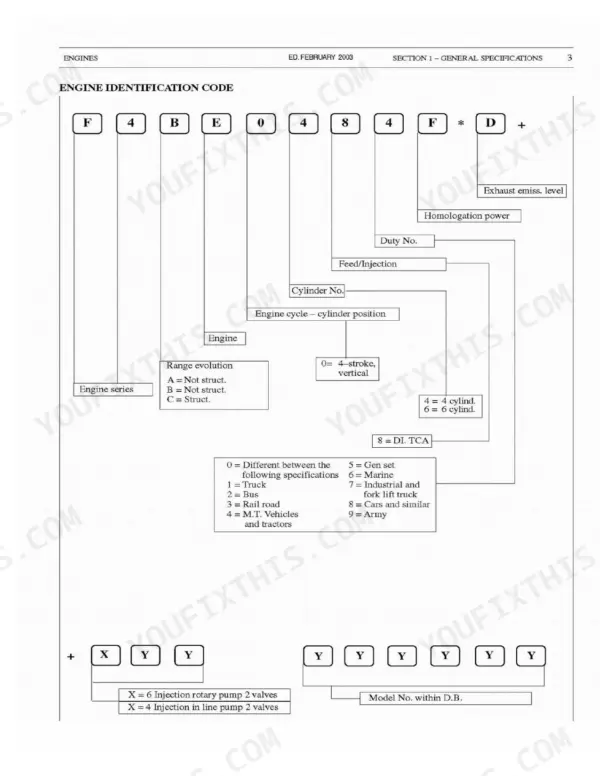
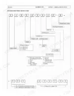
| General Specifications | 12-23 | Engine ID Code, Specific Engine Code, Lubricating Circuit, Oil Vapour Recirculating System, Cooling Circuit System, Boost Feeding Diagram |
| Feed | 24-35 | Injection Feed System, Rotary Pump, Feed Pump, Priming Pump, Fuel Filter, Mechanical Pump Unit |
| General Information and Clearance Data | 36-41 | Mechanical Feed Pump, Clearance Data, 4-Cylinder Engine Specs, 6-Cylinder Engine Specs |
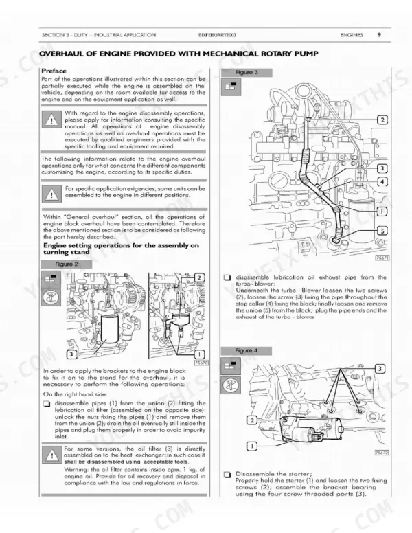
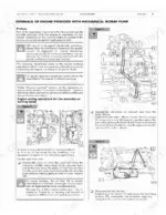
| Overhaul of Engine with Mechanical Rotary Pump | 42-73 | Engine Disassembly, Application Components, Rotary Pump Disassembly, Feed System Bleed, Power Take-Off |
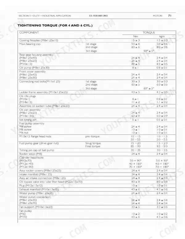
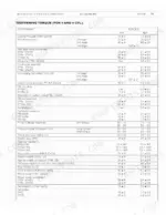
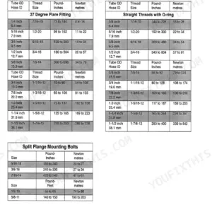
| Overhaul of Engine with Mechanical In-Line Pump | 74-107 | In-Line Pump Disassembly, Engine Assembly, Feed System Bleed, Power Take-Off, Tightening Torque |
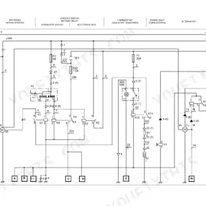
| Electrical Equipment | 108-117 | Electrical Component Layout, Cooling Liquid Temperature Sensor, Starter, Ksb Water Temperature Sensor, Alternator |
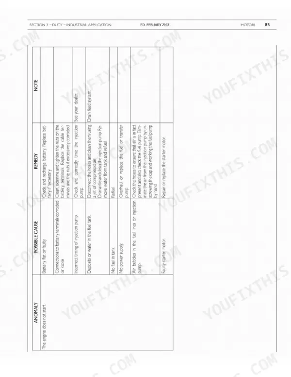
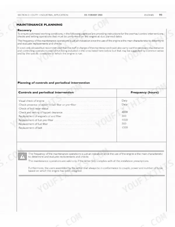
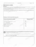
| Troubleshooting and Maintenance Planning | 118-135 | Engine Anomalies, Troubleshooting, Maintenance Planning, Daily Checks, Maintenance Procedures |
| Overhaul and Technical Specifications | 136-171 | Cylinder Unit, Timing System, Output Shaft, Connecting Rod-Piston Assembly, Valves, Valve Springs |
| Tools | 172-175 | Crankshaft Rear Seal Puller, Crankshaft Rear Seal Installer, Crankshaft Front Seal Puller, Crankshaft Front Seal Installer, Injector Puller, Injector Pump Puller |
| Appendix | 176-180 | Standard Safety Prescriptions, Prevention of Injury, During Maintenance, Respect of the Environment |
Quick Reference Specifications
| Specification | Value | Page |
|---|---|---|
| Thermostat start of opening | 81±2 °C | p. 40 |
| M12 x 70 bolt torque | 50 Nm + 90 deg | p. 61 |
| M12 x 140 bolt torque | 40 Nm + 180 deg | p. 61 |
| Suction valves working slack | 0.30 ± 0.05 mm | p. 93 |
| Exhaust valves working slack | 0.55 ± 0.05 mm | p. 93 |
| Oil bypass valve into lube filter head | 80 ± 8 Nm | p. 106 |
| Fuel pump assembly M8 screw | 24 ± 4 Nm | p. 106 |
| Fuel pump assembly M6 screw | 10 ± 1 Nm | p. 106 |
| KSB Water temperature sensor setting contact opening | 32±2 °C | p. 111 |
| Fuel filter replacement torque | 5-10 Nm | p. 133 |
| Alternator current delivered | 90A | p. 113 |
Case 445/M2, 445T/M2, 668T/M2 Common Problems This Manual Covers
Case 445/M2 engine cranks strong but will not start after replacing the fuel filter or running dry
Bleed the feed system following the procedure in the rotary pump section starting on page 44. Crack the bleed screw, work the priming pump until fuel flows without bubbles, then close it. If the filter was just changed, verify it is tightened to 5-10 Nm per page 133 before bleeding again.
Manual Section: Overhaul of Engine Provided with Mechanical Rotary Pump p. 44Coolant temperature climbs past normal within twenty minutes, overflow bottle pushing coolant out
Check coolant level cold and inspect hoses for seepage before condemning parts. Pull the thermostat and test it in heated water; it must start opening at 81±2 °C per page 40. Replace it if it stays shut, then work through the overheating chart on page 120 if temperature still climbs.
Manual Section: Troubleshooting p. 120Loud tappet clatter from the valve cover at idle, worse when engine is cold
Remove the valve cover and set tappet clearance with the engine cold. Adjust suction valves to 0.30 ± 0.05 mm and exhaust valves to 0.55 ± 0.05 mm as listed on page 93. Rotate the crank to bring each cylinder to compression TDC before checking its pair of valves.
Manual Section: Maintenance Procedures - Checks and Controls p. 93Engine down on power under load, black smoke, air cleaner restriction indicator showing red
Check the air cleaner element and dust unloader valve first; a plugged element starves the engine fast. Drain water from the fuel filter bowl, then replace the filter element and tighten it to 5-10 Nm as shown on page 133. Follow the low-power troubleshooting chart on page 120 if smoke continues.
Manual Section: Maintenance Procedures - Replacement p. 133Hard starting below freezing with heavy white smoke until the engine warms up
Test the KSB water temperature sensor before blaming glow plugs. Contacts are set to operate at 32±2 °C as specified on page 111; a stuck sensor disables the cold-start advance. Verify battery voltage at the starter while cranking and confirm alternator output, rated at 90A on page 113.
Manual Section: Electrical Equipment p. 111Frequently Asked Questions
What are the torque specifications for the cylinder head bolts on the 445/M2 engine?
The cylinder head bolts must be torqued in stages. First, tighten all bolts to a snug torque, then apply 50 Nm + 90 degrees for M12x70 bolts and 40 Nm + 180 degrees for M12x140 bolts, following the stitching pattern from the centre bolts outward. p. 161
What are the replacement specifications for the engine oil filter?
When replacing the oil filter, manually start the filter on the bearing union until counter-boring, then further screw it up by 3/4 of a turn. Ensure the fixing ring is lubricated with engine oil before installation. p. 156
What is the correct intake and exhaust valve clearance for the engine?
The working slack for the intake valves is 0.30 ± 0.05 mm, and for the exhaust valves, it is 0.55 ± 0.05 mm. p. 131
What is the engine oil capacity for the 4-cylinder engine?
The engine sump capacity is 8.5 liters, and the total capacity including the filter is 9.5 liters. p. 39
What is the injection pressure for the 4-cylinder engine?
The injection pressure is 245 bar for the F4GE0404A*D6 engine and 260 bar for other models. p. 138
Do I get instant access to this Case 445 Service Manual?
You get a 180-page scanned PDF that downloads instantly after checkout. Open it on your laptop, tablet, or phone, and bring it right to the shop floor.
Am I free to print this Case 445 Service Manual?
Zero restrictions. The PDF is DRM-free. Print whatever sections you need to take out to the shop. Standard letter or A4 paper works.










Reviews
There are no reviews yet.