
Part of the Case Repair Manuals.
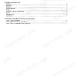
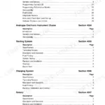
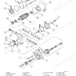
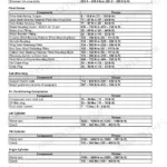
This is the factory service manual for the Case 788, 788 Plus, 988 and 988 Plus excavators, and one book covers both the crawler and the wheeled versions, which is rare and handy if you run mixed iron. Be clear on what it is: a composite binder built from separately numbered reference booklets tied together by a master contents sheet, so there is no single publication number - the cover reads 'Service Manual Cre 7-79415'. Inside you get engine removal and installation, the full electrical system with fault finding by circuit, undercarriage, drive train, both hydraulic sections with pressure setting procedures in bar, and cab work. Revision No. 1, issued 04-01, updates the electrical section and rides at the back.
What's Inside This Case 788, 788 Plus, 988, 988 Plus Manual
| System | Pages | Key Topics |
|---|---|---|
| General Information | 1-64 | Machine Identification, Service Precautions, Standard Maintenance Intervals, Reference Booklet Numbering, Master Table of Contents |
| Engine Removal and Installation | 65-94 | Step-By-Step Engine Removal and Refitting for the 788 and 988, Lifting Points, Coupling and Hose Disconnection Order |
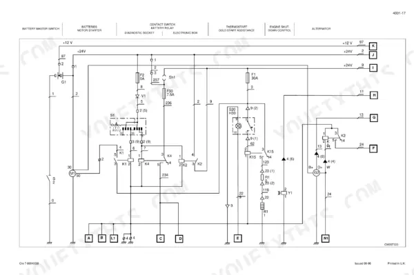
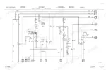
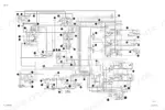
| Electrical System | 95-408 | Schematic Symbols, Electrical Cabinet Printed Circuit, Wiring by Circuit, Sensors and Senders, Instrument Panel, Fault Finding by Circuit |
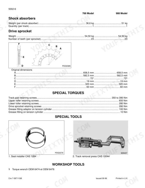
| Undercarriage | 409-430 | Track Chain, Rollers, Idler and Recoil, Sprocket, Track Tension |
| Drive Train | 431-600 | Travel Motor and Reduction Gear, Swing Motor and Swing Reduction, Axles and Final Drives on the Wheeled Version |
| Undercarriage Hydraulics | 601-700 | Centre Swivel Joint, Travel Circuit, Track Motor Lines, Brake and Parking Circuits on the Wheeled Excavator |
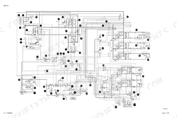
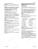
| Upperstructure Hydraulics | 701-1010 | Main Pumps and Regulators, Control Valve Blocks, Boom, Arm and Bucket Circuits, Pilot Control, Pressure Setting and Testing Procedures |
| Upperstructure and Cab | 1011-1046 | Cab Removal, Glass Replacement, Counterweight, Covers and Guards, Operator Station Components |
| Revision No. 1 - Electrical System Update | 1047-1146 | Revised Electrical Section Issued 04-01, Updated Schematic Symbols, Standard and Optional Electrical Cabinet Printed Circuit Descriptions |
Quick Reference Specifications
| Specification | Value | Page |
|---|---|---|
| Attachment limiter pressure | 390 to 425 bar / 380 to 400 bar | p. 733 |
| Boom raising pressure | 390 to 420 bar / 410 to 440 bar | p. 733 |
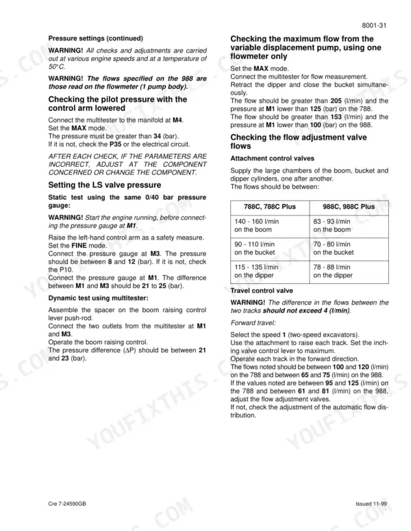
| Maximum pump pressure in Max mode | under 125 bar / under 100 bar | p. 731 |
| Pilot circuit pressure in Max mode | over 34 bar | p. 731 |
| Load sensing valve pressure in Fine mode | 8 to 12 bar | p. 731 |
| Load sensing valve pressure difference M1 to M3 | 21 to 25 bar | p. 731 |
| Proportioning valve pressure, Auto and Low idle | 19.5 to 23.5 bar | p. 726 |
| Proportioning valve pressure, Max mode | 5.5 to 9.5 bar | p. 726 |
| Proportioning valve pressure, Auto idle | 23 to 27 bar | p. 728 |
| Proportioning valve pressure, Low idle | 26 to 30 bar | p. 728 |
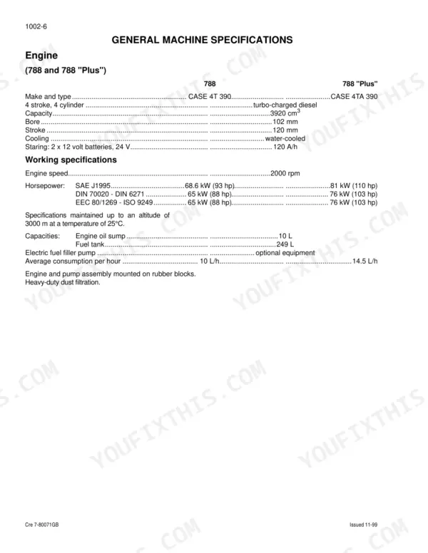
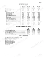
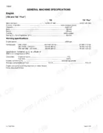
| Rated power to SAE J1995 | 68.6 kW (93 hp) / 81 kW (110 hp) | p. 22 |
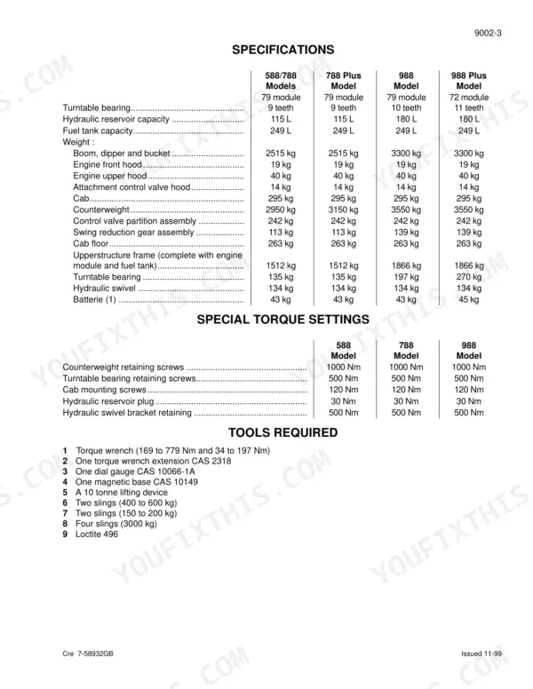
| Fuel tank capacity | 249 litres | p. 22 |
| Average fuel consumption | 10 L/h on the 788, 14.5 L/h on the 788 Plus | p. 22 |
| Engine displacement | 3920 cm3 / 5880 cm3 | p. 22 |
| Engine bore and stroke | 102 mm bore, 120 mm stroke | p. 22 |