
Part of the Case Repair Manuals.
Case issued this 886 page book as publication 8-66102, the factory Case 1818 service manual PDF covering the 1818 Uni-Loader in both its Onan P218 gasoline and Kubota D850 diesel builds. Foldout electrical and hydraulic schematics ride in the rear pocket, one wiring layout per engine, tracing circuits from the key switch through the starter, charging system, and gauges. Hydrostatic troubleshooting works the drive from piston pump through motor, sprockets, chains, and axles, while the hydraulics section rebuilds the loader control valve, auxiliary valve, and cylinders. Set rocker shaft bush clearance between 0.0005 and 0.0026 inch, and pull grade 5 half inch hardware to 80 to 96 pound feet. A dead hydrostat stops the whole job. Bookmarked and searchable by keyword, this PDF puts the correct procedure in front of you and gets your 1818 running again.
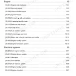
What's Inside This Case 1818 Manual
| System | Pages | Key Topics |
|---|---|---|
| General | 4-41 | Safety Rules, Service Manual Introduction, Torque Specifications, Engine Specifications |
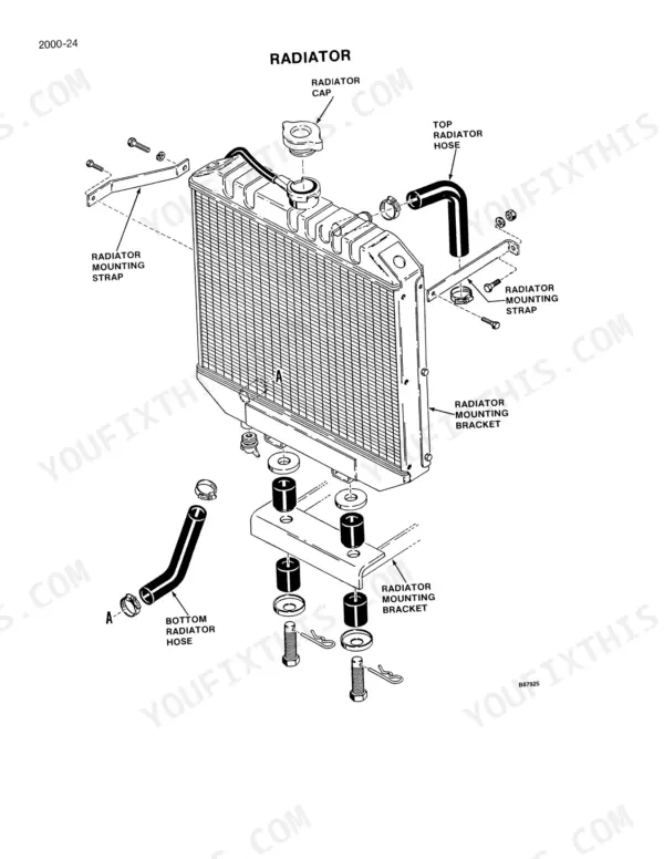
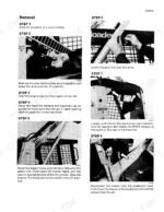
| Engine Removal and Installation | 42-71 | Gasoline Engine Removal, Gasoline Engine Installation, Diesel Engine Removal, Diesel Engine Installation, Radiator Removal, Radiator Installation |
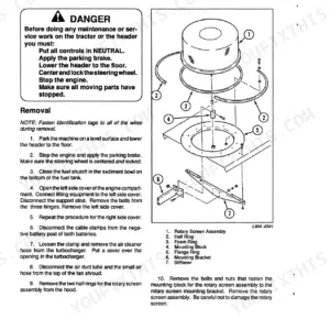
| Engine Accessories | 72-77 | Air Cleaner, Spark Arrester Muffler, Muffler Installation |
| Onan P218 Cylinder Head, Valves, and Camshaft | 78-125 | Cylinder Head Removal, Valve Clearance Adjustment, Camshaft Inspection, Governor Control, Camshaft Bushing Replacement |
| Kubota D850 Cylinder Head and Valve Train | 126-175 | Cylinder Head Removal, Valve Guide Replacement, Rocker Shaft Assembly, Valve Clearance Adjustment |
| Engine Camshaft and Fuel Camshaft (Kubota D850) | 176-207 | Camshaft Removal, Idler Gear Inspection, Fuel Camshaft Assembly, Governor Lever Assembly |
| Cylinder Block, Pistons, and Connecting Rods (Onan P218) | 208-239 | Piston Removal, Cylinder Liner Inspection, Piston Ring Inspection, Connecting Rod Inspection |
| Cylinder Block, Liners, Pistons, and Connecting Rods (Kubota D850) | 240-267 | Cylinder Liner Machining, Piston Ring Inspection, Connecting Rod Inspection, Piston Installation |
| Crankshaft, Main Bearings, Flywheel, and Oil Seals | 268-469 | Crankshaft Removal, Main Bearing Replacement, Flywheel Inspection, Oil Seal Replacement, Lubrication Components |
| Fuel Systems | 470-565 | Carburetor and Fuel Pump, Fuel Pump and Injection Pump, Fuel Injectors and Glow Plugs |
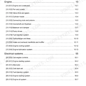
| Electrical | 566-704 | Removal and Installation for Electrical Components, Electrical Specifications and Troubleshooting, Electrical Schematics, Instruments and Gauges, Battery |
| Power Train | 705-778 | Removal and Installation of Power Train Components, Maintenance, Hydrostatic System Troubleshooting, Piston Pump, Motor, Sprocket, Chains, And Axles |
| Hydraulics | 779-847 | Removal and Installation of Hydraulic Components, Maintenance, Hydraulic Schematics, Specifications and Troubleshooting, Cleaning the Hydraulic System, Hydraulic Pump |
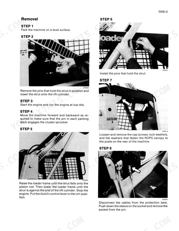
| Mounted Equipment | 848-881 | Pedals and Levers, Loader, ROPS Canopy, Seat Belts, And Operators Compartment, Auxiliary Hydraulic Installation |
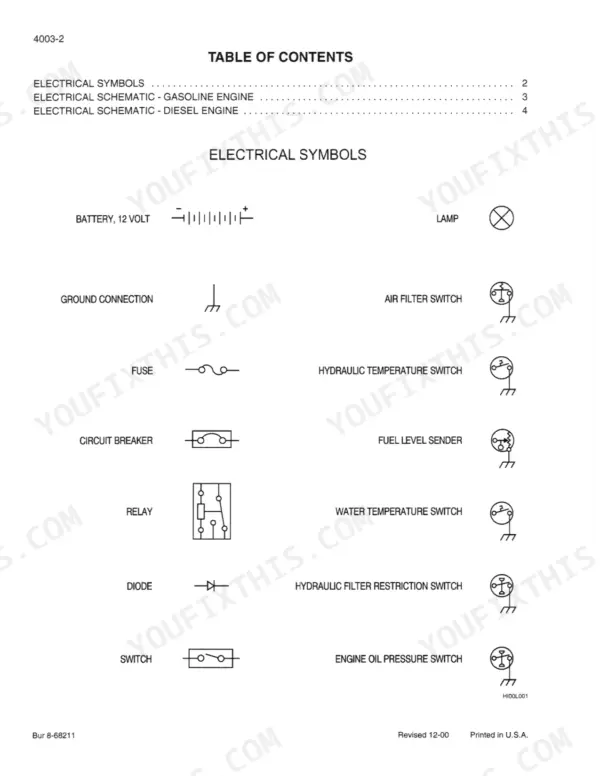
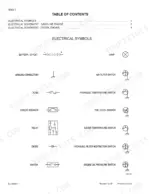
| Rear Pocket | 882-886 | Electrical Schematic, Gasoline Engine, Diesel Engine, Hydraulic Schematic, Electrical Schematic Foldout Gasoline and Diesel Engines |
Quick Reference Specifications
| Specification | Value | Page |
|---|---|---|
| Grade 5 Bolts, Nuts, and Studs (1/4 in) | 9-11 Pound-Feet | p. 9 |
| Grade 5 Bolts, Nuts, and Studs (5/16 in) | 17-21 Pound-Feet | p. 9 |
| Clearance Between Shaft And Bush (Rocker Shaft) | 0.0005 to 0.0026 inch | p. 26 |
| Clearance Between Shaft And Bushes (Idler Gear) | 0.0008 to 0.002 inch | p. 27 |
| Ignition coil resistance (primary) | 2.90 to 3.60 ohms | p. 589 |
| Ignition coil resistance (secondary) | 14,500 to 19,800 ohms | p. 589 |
| Charge pressure for each piston pump (Neutral) | 150 psi (1034 kPa, 10.3 bar) minimum | p. 720 |
| Charge pressure for each piston pump (loaded) | 100 psi (689 kPa, 6.8 bar) minimum | p. 720 |
| Detent stud torque | 5 to 8 pound-feet (7 to 10 Nm) | p. 821 |
| Allen screws for detent housing torque | 10 to 13 pound-feet (13 to 17 Nm) | p. 821 |
| Engine Oil Change Interval (Gasoline) | 25 hours | p. 20 |
| Engine Oil Change Interval (Diesel) | 100 hours | p. 392 |
Case 1818 Common Problems This Manual Covers
Case 1818 loses drive on one side while bucket and other hydraulics still work
Test charge pressure at the dead pump first. Install a gauge and verify at least 150 psi (1034 kPa) in neutral and 100 psi (689 kPa) under load, following the hydrostatic procedure on page 720. Check case drain pressure too; anything over 25 psi (172 kPa) means internal leakage, so plan on new seals or a pump rebuild.
Manual Section: Hydrostatic System Troubleshooting p. 720Loud whining and heavy vibration from the rear pump area under load
Check the reservoir oil level and inspect the suction line for collapse or air leaks; cavitation makes that whine and will wreck the pump fast. If the noise continues with clean oil, pull the gear pump, measure gear width against the 0.510 inch (12.9 mm) spec on page 815, and inspect the housing pockets for scoring.
Manual Section: Hydraulics p. 815Drive belt smokes and burns off within minutes whenever travel is engaged
Verify the drive pumps turn freely before blaming the belt. Bar the pump shaft over by hand with the belt off; binding means internal pump failure. Confirm charge pressure holds 150 psi (1034 kPa) minimum in neutral per the checks on page 720, and inspect the brake pins for one stuck and dragging the drivetrain.
Manual Section: Power Train p. 720Gasoline engine cranks strong but will not fire, no spark at the plugs
Test the ignition coil before throwing parts at it. Measure primary resistance across the coil terminals; spec is 2.90 to 3.60 ohms with secondary at 14,500 to 19,800 ohms, listed on page 589. Replace any coil outside those ranges, then work through the starting circuit and ignition module checks in the same electrical section.
Manual Section: Electrical Troubleshooting p. 589Loader control lever pops out of float detent or will not hold position
Remove the detent housing from the loader control valve and inspect the balls, spring, and sleeve for wear; install a detent kit if they are grooved. On reassembly, torque the detent stud to 5 to 8 pound-feet (7 to 10 Nm) and the housing Allen screws to 10 to 13 pound-feet (13 to 17 Nm) per page 821.
Manual Section: Hydraulics p. 821Frequently Asked Questions
What are the torque specifications for Grade 5 bolts, nuts, and studs on a Case 1818 Uni-Loader?
For 1/4 inch Grade 5 bolts, nuts, and studs, the torque specification is 9-11 pound-feet (12-15 Newton metres). For 1/2 inch bolts, the torque is 80-96 pound-feet (109-130 Newton metres). p. 9
What is the fuel tank capacity for the 1818 Uni-Loader?
The fuel tank capacity for the 1818 Uni-Loader is 8.5 U.S. gallons (32.2 litres). p. 13
What is the correct valve clearance for the Onan P218 engine?
The valve clearance for the Onan P218 engine when cold is 0.005 inch (0.13 mm) for the intake valve and 0.013 inch (0.33 mm) for the exhaust valve. p. 18
How often should the chain compartment oil be changed?
The oil in each chain compartment must be changed after every 500 hours of operation or yearly. p. 718
What is the procedure for checking the charge pressure in the Case 1818 hydrostatic system?
To check charge pressure, run the engine at full throttle with control levers in NEUTRAL. The pressure must be 150 psi (1034 kPa, 10.3 bar) minimum. If the pressure is less than specified, inspect the charge relief valve components. p. 721
Do I get instant access to this Case 1818 Service Manual?
Straight to your device: 886 pages of searchable Service Manual, downloadable the moment payment goes through.
Can I print this Case 1818 manual?
No restrictions at all. Print individual pages, full chapters, or the entire manual. The PDF is completely unlocked.









Reviews
There are no reviews yet.