


Part of the Case Repair Manuals.
Need factory-level procedures for your Case Corporation 1470? This 373-page service manual (OEM #9-85831) covers the 1470 tractor from the 504 BDT engine through the 8-speed power train and full hydraulic system. Inside: hydraulic schematics detailing the three-point hitch and hydraulic control valve, plus wiring diagrams covering the alternator, voltage regulator, and starter motor. Open to the procedures section and you get step-by-step teardown on Robert Bosch fuel injection pumps, Roosa Master injectors, caliper brakes, and the 15-inch traction clutch, backed by page after page of exploded views and torque tables. Hot tappet clearance checks in at .020 inch; hold rocker arm shaft O.D. to .872 to .873 inch and dial transmission bearing preload to 4 to 8 inch-pounds before buttoning anything up. Your machine is down. Get the right numbers, not forum guesses. Download now, open on any device, and bring it straight to the shop floor.
What's Inside This Case 1470 Manual
| System | Pages | Key Topics |
|---|---|---|
| General | 4-27 | Detailed Specifications (Cylinder Head and Valves, Engine Block, Cooling System, Engine Oil Filter, Steering, Air Cleaner, Fuel System, Brakes, Hydraulics, Transmission, Special Torques) |
| Engines | 28-95 | Cylinder Head and Valves, Engine Block Assemblies, Cooling System - Engine Oil Filter |
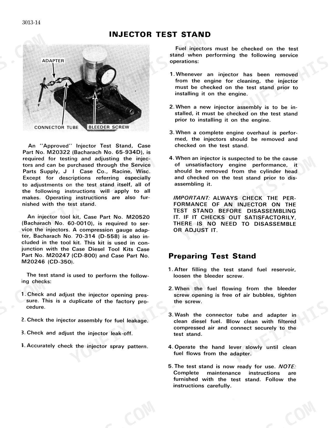
| Fuel System | 96-141 | Fuel System and Filters, Robert Bosch Fuel Injection Pumps, Roosa Master Fuel Injectors |
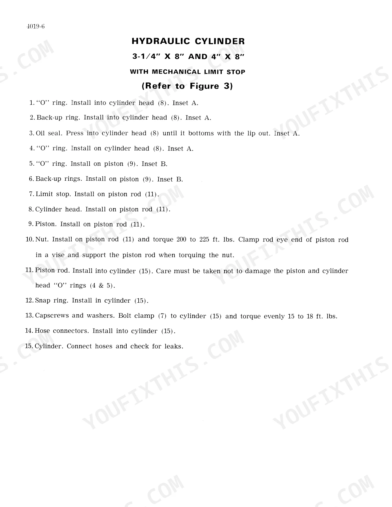
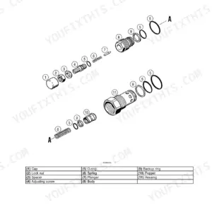
| Hydraulic | 142-215 | Break-Away Couplings and Portable Cylinders, Three Point Hitch System, Hydraulic Control Valve and System |
| Steering | 216-253 | Steering Flow Divider, Front Steering Valve, Front Steering Cylinders, Rear Steering Valve, Rear Steering Cylinder, Steering Axle Adjustment |
| Power Train | 254-349 | 8-Speed Transmission, 15" Traction Clutch, Independent PTO, Differentials and Drive Shafts, Planetaries and Axles |
| Brakes | 350-369 | Master Cylinder, Caliper Brakes, Brake Disc, Parking Brake |
| Electrical | 370-373 | Batteries, Alternator, Voltage Regulator, Starter Motor, Lights |
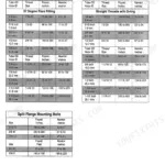
Quick Reference Specifications
| Specification | Value | Page |
|---|---|---|
| Bearing preload (Input, Speed Control Idler, Intermediate and Output Shafts) | 4 to 8 inch pounds | p. 289 |
| O.D. of shaft | .872" to .873" | p. 15 |
| Tappet clearance (Hot) | .020" | p. 13 |
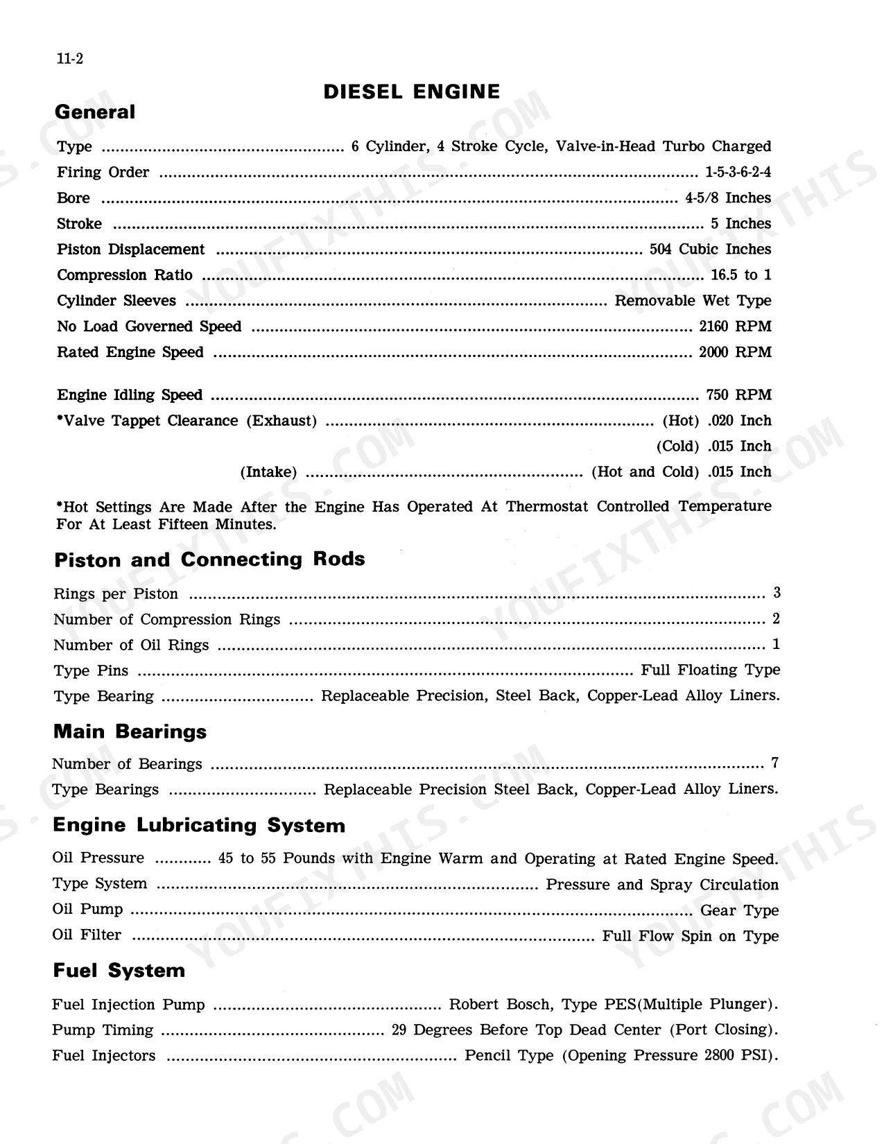
| Engine Piston Displacement | 504 Cubic Inches | p. 5 |
| Engine Rated Speed | 2000 RPM | p. 5 |
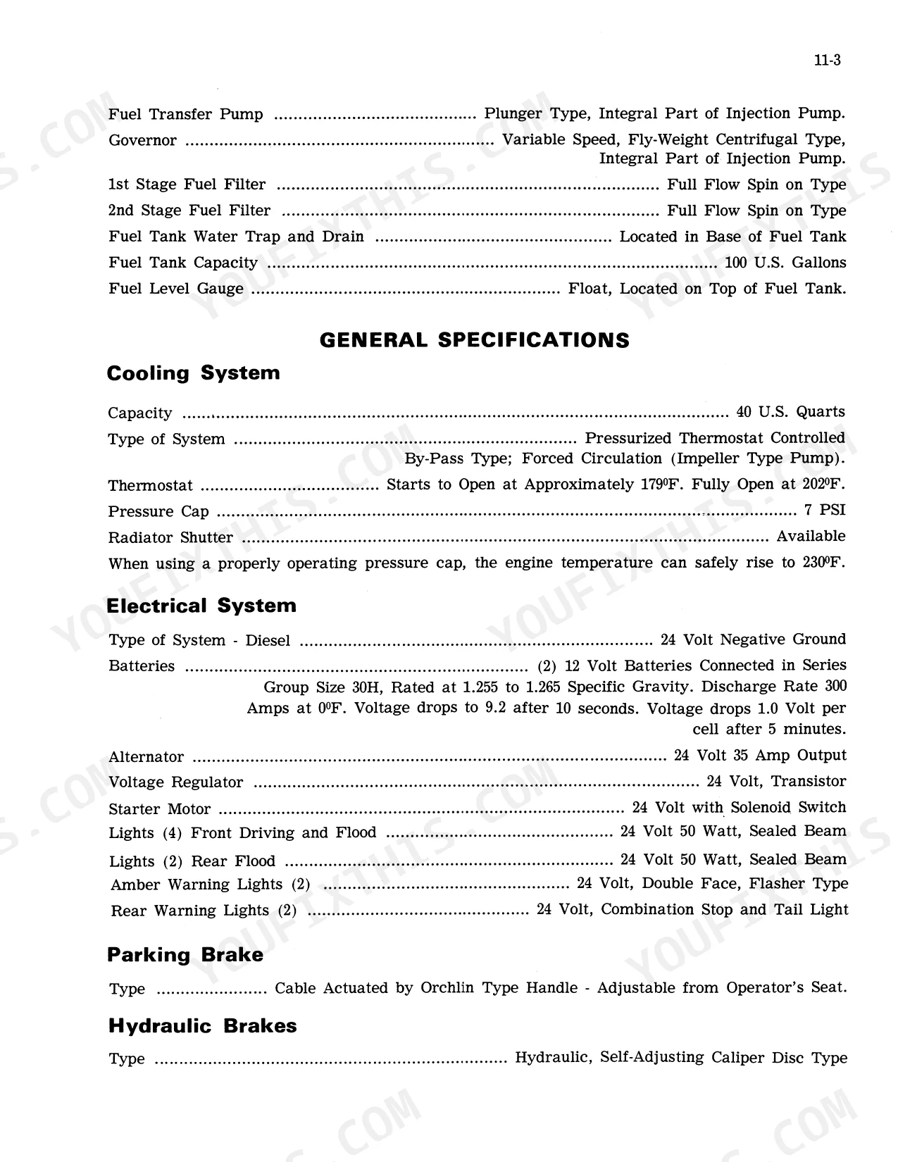
| Cooling System Capacity | 40 U.S. Quarts | p. 6 |
| Remote Hydraulic System Relief Valve Pressure | 2050 to 2250 PSI | p. 7 |
| Wheel Lug Nut Torque | 250 Ft. Lbs. | p. 8 |
| Brake Master Cylinder Bore | 1.25" Bore | p. 21 |
| Cylinder Head Bolts Torque | 200 to 210 ft. lbs. | p. 24 |
| Parking Brake Pinion Shaft Nut Torque | 800 to 1100 ft. lbs. | p. 25 |
| PTO Shaft to Attaching Flange Nut Torque | 200 to 250 ft. lbs. | p. 26 |
Case 1470 Common Problems This Manual Covers
Transmission jams in two gears simultaneously, only disengages at crawling speed
Drain the transmission and pull the shift linkage cover. Inspect the shift forks and synchronizer assemblies for bent fingers or worn blocking rings. Adjust external linkage per before condemning internal parts. If binding persists after linkage correction, disassemble the shift mechanism and replace damaged synchronizer components.
Manual Section: Transmission Service & AdjustmentsFront steering relief valve piston sticks or spring falls out during operation
Remove the front steering relief valve and disassemble the valve body. Inspect all O-rings for cuts or swelling and replace the full O-ring kit. Check the piston bore and piston OD for burrs; stone any high spots until the piston slides freely by hand. Verify system relief pressure after reassembly falls within 1650 to 1750 PSI (page 223).
Manual Section: Steering System Service & Adjustment p. 223Rocker arm shaft clearance out of spec causing valve train noise or uneven idle
Remove the valve covers and measure rocker arm shaft OD with a micrometer. Acceptable shaft OD is .872" to .873" (page 15); shafts below that range are worn and must be replaced. After installing new shafts, adjust tappet clearance with the engine hot to .020" (page 13) and torque cylinder head bolts to 200 to 210 ft. lbs. (page 24) if the head was disturbed.
Manual Section: Cylinder Head and Valves p. 15Hydraulic system pressure erratic or oil delivery drops under load
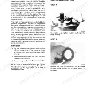
Check hydraulic fluid level first, then pull the hydraulic pump for bench testing using the disassembly and inspection steps starting. Measure internal clearances against spec and look for scored wear plates or cracked seals. Verify remote hydraulic system relief valve pressure is set to 2050 to 2250 PSI (page 7); adjust or replace the relief valve before condemning the pump.
Manual Section: Hydraulic Pump Service & TroubleshootingFrequently Asked Questions
What are the recommended service intervals?
Service intervals vary by component. For the air cleaner, the dust cup should be checked daily or every 10 hours, and the element serviced when the red signal appears. The hydraulic reservoir inlet filter and transmission oil filter should be changed after the first 20 hours, then every 1000 hours, and the breather element every 240 hours. p. 88, 156, 256
What fluids and capacities does this machine require?
The cooling system capacity is 40 U.S. Quarts, and the engine oil filter capacity is 1 U.S. Quart. The fuel tank holds 100 U.S. Gallons, requiring Number 2 Diesel Fuel with specific properties like a minimum API Gravity of 30. Brake fluid should be 70 R1 Heavy Duty, and planetary axles require 3 Quarts of SAE 90EP oil. p. 6, 9, 21, 349
How to troubleshoot engine won't start?
Troubleshooting an engine that won't start involves checking several key areas. This includes verifying the correct injection pump, proper engine 'Run-In', and appropriate lubricating oil viscosity in both the engine and transmission. Other potential issues are plugged air cleaners, partially plugged fuel tank breathers, closed fuel filter bleed valves, lack of fuel to injectors due to plugged filters or air/water, incorrect fuel pump timing, improper valve tappet clearance, faulty injectors, loss of compression, or misadjusted fuel shut-off control. p. 107
How do you fix case 1470 transmission bearing grinding noise and gear jumping in working range?
Remove the transmission and measure bearing preload on the Input, Speed Control Idler, Intermediate, and Output Shafts. Preload must read 4 to 8 inch pounds (page 289); anything outside that range means the bearing is shot or improperly shimmed. Disassemble per the Transmission Service section, inspect bearing races and gear teeth for spalling, replace worn components, and reset preload before reassembly. p. 289
What format is this manual in?
You get a 373-page searchable PDF that downloads instantly after checkout. Open it on your laptop, tablet, or phone, and bring it right to the shop floor.
Am I able to print pages from this manual?
Yes. The PDF has no DRM restrictions, so print any page or section you need for your shop. Works with any standard printer.
Does this Case Corporation 1470 Service Manual cover the hydraulic system?
Included. Hydraulic system schematics cover all circuits, control valves, and component specifications for the Case Corporation 1470.


Reviews
There are no reviews yet.