
Part of the Case Repair Manuals.
Written for the Case 1420 Axial Flow Combine, this 357-page Case 1420 service manual PDF (OEM ID GSS-1500) follows all ten factory sections, from the engine and separator drives to the operator's cab. Hydraulics fill over a third of the book, covering hydrostatic power steering, the electro-hydraulic control valves and automatic header control, with schematics showing how oil routes to each circuit. Wiring diagrams for the cab and electrical system sit next to troubleshooting charts that take you from symptom to cause. Set separator drive belt to pulley shield clearance at 1.778 mm (0.070 inch), and torque the pulley retaining nut to 251 to 339 N·m (185 to 250 ft. lbs.). A made-up torque figure can cost you the harvest. Bookmarked and text-searchable, the PDF rides along on a phone or laptop in the cab, so the specs stay with your 1420 in the shed or halfway down a wheat field.
What's Inside This Case 1420 Manual
| System | Pages | Key Topics |
|---|---|---|
| Engine and Fuel Tank | 22-27 | Engine |
| Separator Drive Units | 28-57 | Engine PTO Gear Box, Separator Drive Jackshaft |
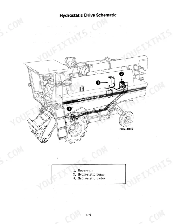
| Hydrostatic Drive | 58-73 | Hydrostatic Drive Pump, Hydrostatic Drive Motor |
| Brakes, Transmission, Differential, Final Drives and Steering Axle | 74-117 | Transmission, Final Drive and Pinion Assembly, Brakes |
| Hydraulic System | 118-247 | Hydrostatic Power Steering, Electro-Hydraulic Control Valves, Automatic Header Control |
| Cutting and Feeding | 248-255 | Feeder Gear Housing Assembly |
| Threshing and Separating | 256-293 | Rotor Drive Gear Case and Torque Sensing Unit, Auger Bed Assembly, Straw Chopper |
| Cleaning System | 294-299 | Cleaning Fan |
| Elevators and Grain Tank | 300-307 | Grain Tank Unloader Vertical Auger |
| Operator's Cab and Electrical System | 308-357 | Air Conditioning System, Wiring Diagrams |
Quick Reference Specifications
| Specification | Value | Page |
|---|---|---|
| Separator drive belt and pulley shield clearance | 1.778 mm (0.070 inch) | p. 47 |
| Pulley retaining nut | 251 to 339 N·m (185 to 250 ft. lbs.) | p. 249 |
| Hydraulic separator clutch idler assembly spring nut adjustment | 12.7 mm (1/2 inch) | p. 49 |
| Motor Cylinder Barrel Spring Test Load | 46.02-56.25 N/mm (262.8-321.2 Lbs.) | p. 59 |
| Motor Cylinder Barrel Spring Test Length | 40.56 mm (1.597 inches) | p. 59 |
| Rubber sleeve nut torque | 67.8 to 81.3 N·m | p. 68 |
| Unloader control cable pull | 178 N (40 lbs.) | p. 303 |
| Unloader upper gear case backlash | 0.10 mm to 0.15 mm (.004 to .006 inch) | p. 304 |
| Hydrostatic Drive Normal Operating Pressure | 37.23 to 38.61 MPa | p. 60 |
| Differential Pinion Shaft End Play | 0.05 to 0.2 mm | p. 76 |
| Air Conditioning Refrigerant Charge (R-12) | 2.4 kg | p. 314 |
| Feeder Gear Housing Gear Backlash | 0.13 to 0.28 mm | p. 249 |
Case 1420 Common Problems This Manual Covers
Case 1420 axial flow combine hydrostatic power steering hard to turn with steering wheel slip
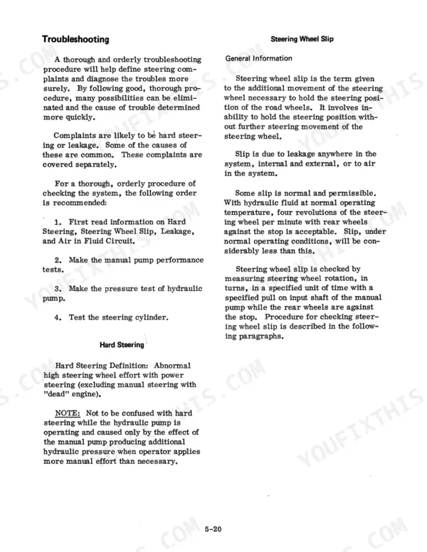
Check the steering circuit for air in the fluid and external leakage before pulling any components, following the hydrostatic power steering troubleshooting steps. Find where the air is getting in, fix every leak you find, then work through the hard steering and wheel slip checks in order so you are back in the field before the weather turns.
Manual Section: Hydrostatic Power Steering TroubleshootingHydraulic reel drive leaking oil, showing no power, or losing speed badly under load
Measure flow to the reel drive and compare it against the 35.9 litres/minute maximum listed on page 230. Trace any oil leakage to its source on the drive. If flow is good but speed still sags under load, treat it as low mechanical efficiency inside the drive before you lose another harvest day.
Manual Section: Hydraulic Reel Drive Troubleshooting p. 230Cab air conditioning giving insufficient cooling, compressor noise and vibration, or clutch slippage
Verify the system holds the full R-12 refrigerant charge of 2.4 kg listed on page 314 before chasing anything else. Check the compressor for noise and vibration, and inspect the clutch for slippage. If the engine is also running hot, work that overheating check too, since the air conditioning chart covers it alongside poor cooling.
Manual Section: Air Conditioning Troubleshooting p. 314Shaft speed monitoring system sensor damaged or out of clearance and the console not working
Inspect each sensor for physical damage and check its clearance before replacing anything. Trace the harness for damaged wiring using the wiring diagram on page 334. At the console, test the connector, fuse, and battery supply, since a dark console can be a power problem rather than a sensor, and that fix gets you rolling faster.
Manual Section: Shaft Speed Monitoring System TroubleshootingAxial flow rotor cracking grain, breaking cobs, leaving unthreshed heads, or losing kernels
Check the grain sample and pin down which symptom you have: damaged grain, cob breakage, unthreshed heads, kernel loss, heavy stems, or fines. Each has its own cause list in the threshing and separation chart, so match yours before adjusting anything. While in there, check the variable pulley spring against its 203 mm (8 in.) expansion length on page 261.
Manual Section: Threshing and Separation ProblemsFrequently Asked Questions
What are the torque specifications for the nuts and bolts on the Case 1420?
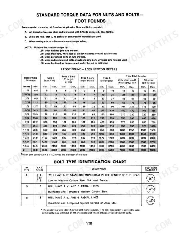
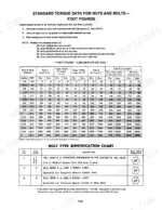
The torque specifications for standard nuts and bolts depend on the bolt type and diameter. For example, a 1/2-inch Type 5 bolt has a torque range of 80 to 90 foot-pounds. Always ensure thread surfaces are clean and lubricated with SAE-30 engine oil before applying torque. p. 11
What torque should the final drive housing-to-axle studs be on a Case 1420 combine?
The recommended torque for the final drive housing-to-axle studs is 163 Newton meters (120 foot-pounds). p. 76
What is the procedure for bleeding the hydraulic brake system?
To bleed the brakes, push the brake pedal down and hold it. Turn the bleed screw to release air and fluid, then tighten the screw before releasing the pedal. Repeat this process until the fluid is clear and free of air, ensuring the master cylinder reservoir is maintained with fluid throughout. p. 111
What is the correct backlash for the separator drive gear?
The correct backlash for the separator drive gear is between 0.102 mm and 0.203 mm (0.004 to 0.008 inches). p. 45
What is the hydraulic fluid reservoir capacity on the Case 1420 combine?
The hydraulic fluid reservoir has a capacity of 19 litres (5 gallons). p. 246
Is this Case 1420 manual a download or a disc?
All 357 pages arrive as one searchable PDF at checkout. Read it at the desk, then take the phone out to the machine.
Can I print just the pages I need from this Case 1420 manual?
Yes. Printing works from any reader and any printer, for your own shop use.









Reviews
There are no reviews yet.