
Part of the Case Repair Manuals.
You have a gauge teed into the backhoe circuit and a relief valve that won't hold. This book gives you the setting: boom piston side 310 bar (4496 psi), bucket rod side 260 bar (3771 psi), swing 205 bar (2973 psi), page 836.
This is the Case «Backhoe loader» volume, Print Number 84428671A1, for the 580T, 580ST, 590ST and 695ST. It covers the Carraro Powershuttle and Powershift transmissions, axles, brakes, hydraulics, steering, cab heating and air conditioning, and the electric diagrams. It also has the DTC warning table. Engine repair is in a separate Engine volume, 87659057A, which is not included.
What's Inside This Case 580T, 580ST, 590ST, 695ST Manual
| System | Pages | Key Topics |
|---|---|---|
| Introduction, Safety Rules and Maintenance | 1-28 | Service Manual Volumes and Print Numbers, Model and Version Table, Index, Accident Prevention, Safety Instructions, Fire, Burn and Waste Disposal Precautions, Maintenance Safety and Tyre Inflation Precautions |
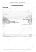
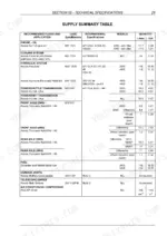
| Technical Specifications | 29-58 | Models and Main Components, Iveco Engine Data for the 580T, 580ST, 590ST and 695ST, Transmission Ratios, Axles, Brakes, Steering, Hydraulic Pumps, Counterweights, Noise and Vibration, Buckets, Tyres, Dimensions, Loader and Backhoe Performance, Maximum Lifting Loads, Supply Summary Table |
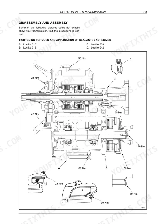
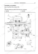
| Powershuttle Transmission | 59-211 | Carraro TLB1 Transmission Specifications, Hydraulic Diagram, Controls, Lubrication, Greasing, Removal From Machine, Disassembly and Assembly with Tightening Torques, Troubleshooting, Repair Times, Special Tools |
| Powershift Transmission | 212-398 | Carraro TLB2 Transmission Specifications, Hydraulic Diagram and Relief Valves, Controls, Lubrication, Greasing, Removal From Machine, Disassembly and Assembly, Troubleshooting, Repair Times, Special Tools |
| Front Axle, 2WD and 4WD (2WS) | 399-459 | 2WD and 4WD Front Axle Specifications, Lubrication and Greasing, Removal From Machine, Disassembly and Assembly, Troubleshooting, Special Tools |
| Front Axle, 4WS (695ST) | 460-536 | 4WS Front Axle Specifications, Lubrication and Greasing, Removal From Machine, Disassembly and Assembly, Troubleshooting, Repair Times, Special Tools |
| Rear Axle, 2WS (580T, 580ST) | 537-604 | Carraro 28.44 Rigid Axle Data, Bevel Gear Backlash and Pinion Bearing Preload, Wet Disc Service Brake Discs, Lubrication and Greasing, Removal From Machine, Disassembly and Assembly with Tightening Torques, Troubleshooting, Repair Times, Special Tools |
| Rear Axle, 2WS (590ST) | 605-670 | Carraro 28.50 Axle: Technical Data, Differential Lock Pressure and Service Brake Specifications, Greasing Points, Axle Removal, Overhaul Sequence with Torque Values, Fault Table, Repair Times and Tools |
| Rear Axle, 4WS (695ST) | 671-764 | Steering Rear Axle Specifications, Lubrication and Greasing, Removal From Machine, Disassembly and Assembly with Tightening Torques, Troubleshooting, Repair Times, Special Tools |
| Brake System | 765-778 | Parking Brake Specifications, Operation, Adjustment, Disassembly and Assembly; Service Brake Specifications and Operation |
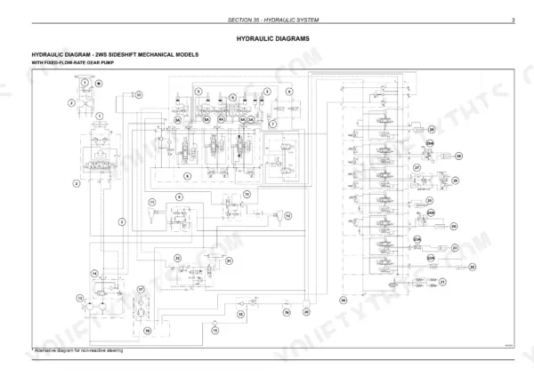
| Hydraulic Diagrams | 779-796 | Hydraulic Diagrams for 2WS and 4WS Sideshift Mechanical and Pilot Models and 4WS Center Pivot Pilot Models, With Fixed-Flow-Rate Gear Pump or Variable-Flow-Rate Piston Pump |
| Hydraulic Pumps | 797-821 | Fixed-Flow-Rate Gear Pump and Variable-Flow-Rate Piston Pump Specifications, Operation, Load Sensing, Removal, Disassembly and Assembly, Tightening Torques |
| Control Valves, Relief Valves and Accumulator | 822-864 | Loader and Backhoe Control Valves, Flow Balancer and Stand-By Pressure, Relief Valve Settings and Operation, Backhoe Pilot Solenoid Valve, Glide Ride Accumulator Precharge Check, Hydraulic Swing System |
| Hydraulic Cylinders | 865-920 | Loader Boom and Bucket Cylinders, 4x1 Bucket Cylinder, Backhoe Boom, Dipper, Bucket and Telescopic Cylinders, Stabilizer Cylinders: Removal, Disassembly and Assembly |
| Chassis | 921-932 | Chassis Description, Removal and Installation of Components Within, Below, Outside and on the Upper Part of the Chassis |
| Steering System | 933-954 | Steering Description, 2WS and 4WS Steering Systems, Power Steering Unit Specifications, Components, Disassembly and Assembly |
| Cab Heating and Air Conditioning | 955-1020 | Heating Controls, Operation, Air Flow Diffusers and Overhaul, Air Conditioning Principles, Controls, Troubleshooting and Testing, Flushing, Draining and Charging the System, Compressor Removal, Overhaul and Troubleshooting |
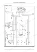
| Electric Diagrams | 1021-1111 | Line Diagrams, Component Lists and Connectors for Powershuttle ROPS and Cab (580T Mechanical Engine), Powershuttle Cab (580ST, 590ST Electronic Engine) and Powershift Cab 2WS and 4WS: Engine, Solenoid Valve, Lights, Work Lights, Wiper, Cab, Quick Coupler, Transmission Control Unit, 4WS Steering and Cold Start Circuits |
| Controls, Instruments and Warning Messages | 1112-1145 | Front Control Panels, Side Instrument Cluster, Anti-Start System, Diagnostic Display Symbols, Setup Menu, Self Test, On-Board Error Code Retrieval, Work Hours, Warning System and Warning Messages Table with DTC Numbers |
| Starting System, Alternator and Battery | 1146-1164 | Starting System Operation, Starter Motor, Alternator Specifications and Operation, Battery Specifications, Replacement, Charge and Electrolyte Check, Booster Battery, Battery Master Switch, Troubleshooting |
| Loader Attachment | 1165-1188 | Loader Controls and Operation, 4x1 Bucket Control, Control Lock, Bucket Self-Levelling, Return to Dig, Safety Strut, Bucket and Forks Removal, Bucket Teeth Replacement, Loader Removal |
| Backhoe Attachment | 1189-1228 | Backhoe Description and Operation, Mechanical and Hydraulic Controls, Sideshift, Backhoe Disassembly, Bucket Replacement, Hydraulic Handling, Hydraulic Diagram, Handling Cylinder Disassembly and Assembly |
Quick Reference Specifications
| Specification | Value | Page |
|---|---|---|
| 580T | ||
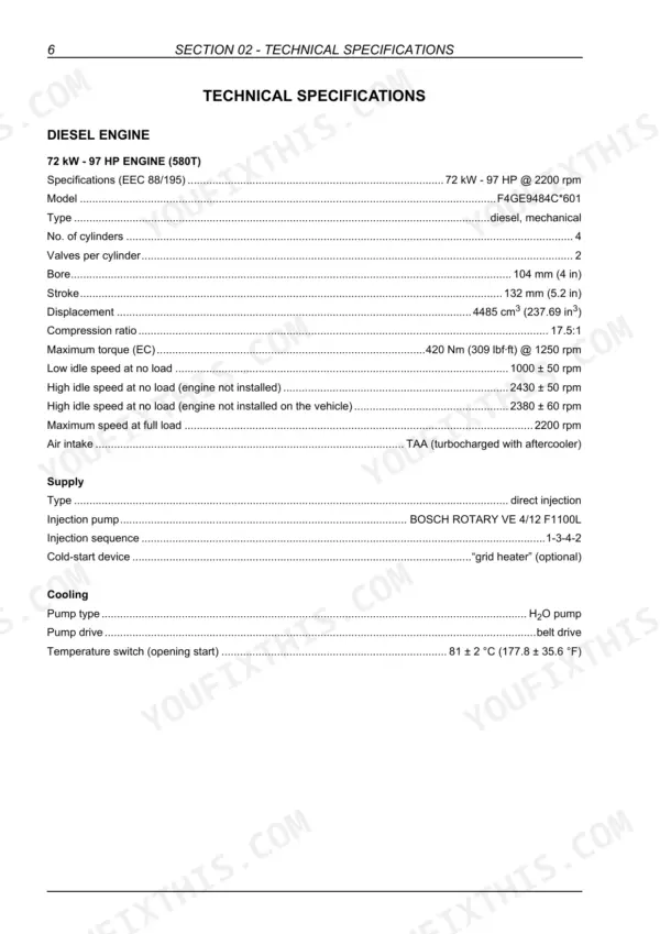
| Engine (580T) | Iveco F4GE9484C*601, 72 kW - 97 HP @ 2200 rpm (mechanical) | p. 34 |
| 580ST | ||
| Engine (580ST) | Iveco F4HE0484G*J102, 72 kW - 97 HP @ 2200 rpm, common rail, EDC7 | p. 35 |
| 590ST, 695ST | ||
| Engine (590ST, 695ST) | Iveco F4HE9484C*J102 (590ST), F4HE9484C*J103 (695ST), 82 kW - 110 HP @ 2200 rpm | p. 36 |
| Maximum torque (590ST, 695ST) | 516 Nm (380.58 lbf·ft) @ 1400 rpm | p. 36 |
| All Models | ||
| Displacement, bore x stroke | 4485 cm3, 104 mm x 132 mm, 4 cylinders | p. 34 |
| Powershuttle transmission | CARRARO TLB1 MPB 2WD (580T), TLB1 MPB 4WD (580ST, 590ST) | p. 37 |
| Powershift transmission | CARRARO TLB2 MPB 4WD (580ST, 590ST), TLB2 MPB 4WS (695ST) | p. 37 |
| Steering system pressure | 170 ÷ 175 bar (2465 ÷ 2538 psi) | p. 39 |
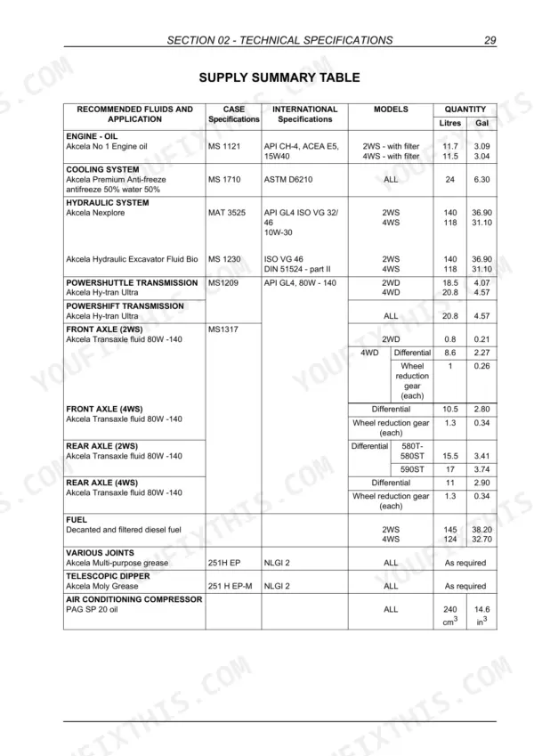
| Engine oil with filter | 11.7 litres (2WS), 11.5 litres (4WS) | p. 57 |
| Cooling system | 24 litres | p. 57 |
| Hydraulic system | 140 litres (2WS), 118 litres (4WS) | p. 57 |
| Fuel tank | 145 litres (2WS), 124 litres (4WS) | p. 57 |
| Powershift transmission oil | 20.8 litres | p. 57 |
| Pump stand-by pressure | 15 bar | p. 825 |
| Loader bucket relief valve (gear pump version) | rod side 240 bar (3481 psi), piston side 165 bar (2393 psi) | p. 831 |
| Backhoe boom relief valve | rod side 240 bar (3481 psi), piston side 310 bar (4496 psi) | p. 836 |
| Backhoe swing relief valve | 205 bar (2973 psi) | p. 836 |
| Glide Ride accumulator precharge | 30 ± 1 bar | p. 859 |
Case 580T, 580ST, 590ST, 695ST Common Problems This Manual Covers
Powershuttle machine does not move
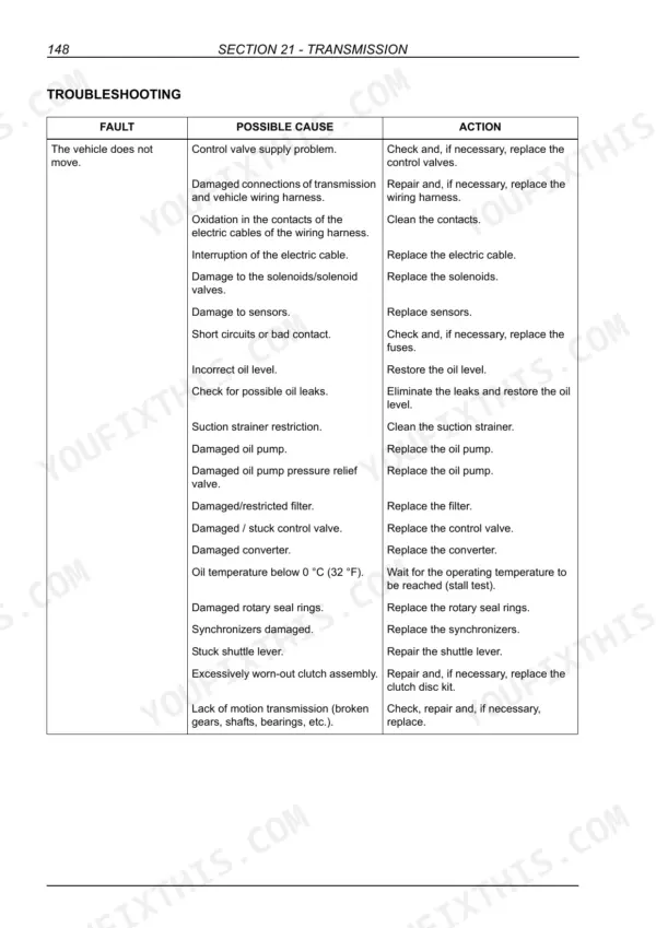
Check the causes listed on page 206: incorrect oil level, a restricted suction strainer (clean it), a restricted filter, a damaged oil pump or pump relief valve, oxidised harness contacts and damaged solenoids or sensors. If the oil is below 0 °C (32 °F), wait for operating temperature (stall test). A damaged converter and a worn clutch assembly are also on the list.
Manual Section: Powershuttle Transmission p. 206Engine will not crank with the key turned and the transmission in neutral
Page 1154 starts with battery charge, then the starter wiring for bad connections or cut cables, then a seized starter. Next, check for +12 V on the white input wire of the starting solenoid, and listen for the solenoid to click. Page 1124 explains the M38 immobiliser: relay No. 2 sits in line with the starter relay/solenoid wire.
Manual Section: Starting System, Alternator and Battery p. 1154Cab air conditioning is not cooling
Page 979 gives the preliminary checks. Run the engine at 1000-1200 rpm for 10 minutes with maximum cooling, the blower on high and the heater OFF. The compressor clutch should click in when you switch from OFF to ON. If it doesn't, suspect the pressure cut-out switches or the clutch. Also check belt tension and that the condenser, evaporator fins and cab filter are clean. The refrigerant is HFC 134a.
Manual Section: Cab Heating and Air Conditioning p. 979Front axle ring gear with broken, pitted or worn teeth
The troubleshooting table on page 455 matches each symptom to a cause. A broken tooth points to excessive load (replace the bevel gear set), incorrect backlash (adjust the bevel gear set backlash) or a loose pinion nut (tighten it). Pitted teeth or an overheated ring gear and pinion mean poor or contaminated lubrication or a low oil level. That calls for a new bevel gear set. Replace worn bearings and top up the oil.
Manual Section: Front Axle, 2WD and 4WD (2WS) p. 455Frequently Asked Questions
What does a warning or DTC code mean on a Case 590ST?
The warning messages table runs from page 1139 to page 1145. Each row gives the lamp, alarm, display, condition, DTC, source (VCM or ECU), priority and colour. DTC 1002 VCM means coolant has been above 111 °C for 5 seconds, with a red STOP lamp. DTC 3028 ECU is engine oil pressure too low. DTC 1008 VCM is transmission oil pressure too low: the switch has been closed to ground for 25 seconds with the engine running. DTC 1009 VCM means transmission oil has been above 115 °C for 5 seconds. The battery voltage codes 1014, 3051 and 3052 are on page 1140. p. 1139
How do I read the stored error codes on a Case 580ST?
Page 1130 shows how the stored codes come up on the diagnostic display. They show page by page (Page 1/6 and so on), each with CODE, OCCURRENCE and TIME. TIME is the hour count of the last occurrence. The display scrolls every 3 seconds unless you press the up or down button. Error code storage is part of the setup menu on page 1126. The warning messages table from page 1139 lists DTC numbers with their source, condition and lamp. p. 1130
What are the relief valve pressures on a Case 580T backhoe?
The loader control valve settings for the gear pump version are on page 831. Bucket rod side is 240 bar (3481 psi), bucket piston side is 165 bar (2393 psi) and the hydraulic speed valve is 165 bar (2393 psi). The 4x1 bucket is 240 bar (3481 psi). The backhoe settings are on page 836: dipper 240 bar (3481 psi), boom piston side 310 bar (4496 psi) and telescopic dipper 124 bar (1798 psi). Page 825 gives the 15 bar stand-by pressure held by the flow balancer valve. p. 836
Where are the wiring diagrams for a Case 695ST?
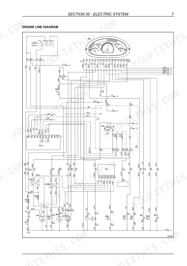
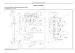
The electric diagrams cover five versions, and the Powershift cab (4WS) set for the 695ST starts on page 1093. Its line diagrams cover the engine, transmission control unit, 4WS steering, solenoid valves, lights, work lights, wiper, heater and radio, backhoe quick coupler and cold start circuits, with component and connector lists. For hydraulics, the fold-out diagrams from page 781 include the 4WS sideshift and 4WS center pivot pilot models. p. 1093
How do I check the Glide Ride accumulator on a Case 580ST?
Page 859 covers the Parker accumulator: 2 litres gas, 1.84 litres oil and a precharge of 30 ± 1 bar. Use nitrogen (N2) only, never oxygen. Check the precharge in the first week after commissioning, then every three months. Let the accumulator stand for at least 15 minutes before you take the final reading. The check is done with charging and measuring kit UCA 380002714, shown on page 860. p. 859









Reviews
There are no reviews yet.