
Part of the Case Repair Manuals.
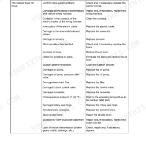
The 650L Tier 3 runs left and right hydrostatic pumps and motors under a drivetrain controller that talks CAN with the engine controller. When that link drops, the crawler will not move. This Case service manual, part number 84276960, works through the fault codes one controller at a time. It also covers hydraulic tests, final drives, brakes, tracks, cab, A/C, blade and ripper.
When the machine is down on a job and there is nobody to call, you need the numbers in front of you. That means relief pressures, pump flow at 2000 RPM, final drive and track torques, fill capacities, and fold-out electrical and hydraulic schematics. This is the October 2009 CNH issue, and it replaces 84260831.
What's Inside This Case 650L Manual
| System | Pages | Key Topics |
|---|---|---|
| Introduction | 1-29 | How to Use the Manual, Basic Instructions, Decimal and Metric Bolt Torque Tables, Hydraulic Fitting Torques, Conversion Factors, Hydraulic Contamination, Loctite Product Chart, Capacities |
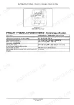
| Primary Hydraulic Power System | 30-98 | Hydraulic Oil and Test Temperature, Neutral and Main Relief Pressures, Circuit Relief Valves, Stack Valve Torques, Calibration and Spool Travel, Hydraulic Pump Specification, Cleaning and Decontaminating, Relief Valve Pressure Setting and Test, Stack Valve Flow Test, Pump Preliminary and Flow Tests |
| Secondary Hydraulic Power System | 99-122 | Relief Valve Exploded and Sectional Views, Pressure Test and Pressure Setting, Disassembly, Visual Inspection and Assembly |
| Electrical Power System | 123-222 | 12 Volt Negative Ground Specification, Battery Specification, Grounding Locations, Fuse and Power Relay Modules, Connector Component Diagrams, Electrical Schematic Frames 01 to 27, Battery, Fuse, Alternator, Battery Switch and Power Outlet Testing |
| Lighting System | 223-230 | Front and Rear Work Lights and Switches Testing, Light Switch Testing |
| Fault Codes: Retrieval and Instrument Cluster Codes | 231-277 | Retrieving and Clearing Fault Codes, Yellow and Red Faults, Fault Code Grouping, AIC Codes for Hydraulic Oil, Transmission Oil and Coolant Temperature, Engine Oil Pressure and Battery Voltage, CAN Time-Out Codes |
| Fault Codes: Drivetrain Controller (DTC) | 278-391 | Pump Solenoid Circuit Codes, Engine Speed Signal, Parking Brake Solenoid, Bump Switches, Directional Control and Joystick CAN Faults, CAN Communication with the Instrument Cluster and Engine Controller, Standstill, Forward and Reverse Checks, Direction Motor Codes |
| Fault Codes: Engine Controller (EDC) | 392-719 | Coolant, Fuel and Oil Temperature Sensors, Boost and Atmospheric Pressure Sensors, Oil Pressure Too Low and Oil Pressure Sensor Codes, Battery Voltage to Engine Controller, Injector and Cylinder Codes, CAN Message Time-Outs, Engine Controller Recovery Codes |
| Engine | 720-736 | Diagnosing Engine Oil Consumption, Oil Consumption Test Forms, Balancer Remove, Timing Adjust, Install and Test |
| Fuel, Air Intake and Lubrication | 737-755 | Fuel Level Sensor Testing, Turbocharger Troubleshooting, Troubleshooting Engine Oil Consumption |
| Hydrostatic Transmission | 756-849 | Reverse Ratio Control, Hydrostatic Pump and Motor Disassembly, Visual Inspection, Assembly and Filling, Reverse Ratio Control Testing |
| Final Drive | 850-920 | Final Drive Torques and Special Tools, Exploded and Sectional Views, Preliminary Test, Removal, Disassembly, Assembly and Installation, Planetary Gearset, Spur Gear, Sandwich Housing |
| Service Brake | 921-930 | Brake Torques, Exploded View, Visual Inspection, Brake Preliminary Test |
| Tracks and Undercarriage | 931-1035 | Drive Sprocket and Steel Track Torques, Case Extended Life Track (CELT) Chain Specification, Track Pad Dimensions, Lower Roller Torque and Wear Dimensions, Upper Roller, Idler, Track Adjuster and Recoil Mechanism, Roller and Idler Leakage Tests |
| Operator Controls and Seat | 1036-1066 | Digital Instrument Cluster and LCD Multi-Function Display, Instrument Panel Testing, Air Suspension and Mechanical Suspension Seat Disassembly, Inspection and Assembly, Seat Suspension Testing |
| User Platform | 1067-1076 | Operator Protective Structure Inspection, ROPS Cab/Canopy Tilt, Windshield and Door Wiper Motors and Switches Testing |
| Heating and Air Conditioning | 1077-1134 | ROPS Heater and Ventilation Testing, A/C Special Tools and Specifications, Pressure/Temperature Chart, Compressor and Magnetic Clutch, Evacuate, Discharge, Charge and Leakage Test, Belt Check and Adjust, Condenser Fan, Expansion Valve, Temperature Sensor and Pressure Switch Testing |
| Safety Accessories | 1135-1141 | Warning Buzzer Testing, Audible Alert Switch and Horn Testing |
| Blade Lift, Tilt and Angle | 1142-1213 | Lift, Tilt and Angle Cylinders, Control Valve and Command Exploded Views, Travel Adjust, Cylinder Disassembly, Visual Inspection and Assembly |
| Ripper and Dozer Blade | 1214-1226 | Ripper Cylinder Exploded View, Disassembly and Visual Inspection, Dozer Blade Cylinder Leakage Test |
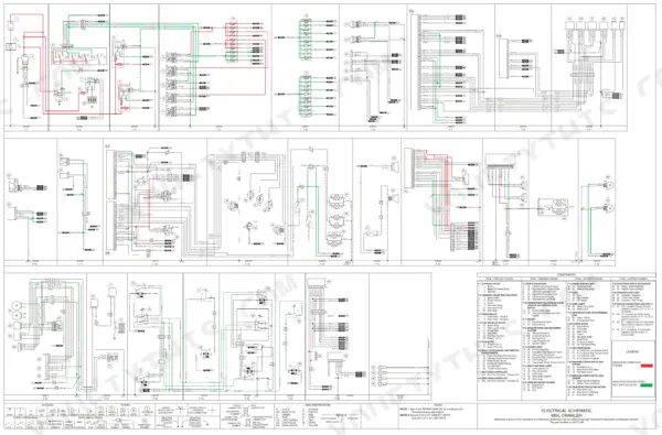
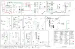
| Electrical Schematic | 1227-1227 | Fold-Out 650L Crawler Electrical Schematic with Wire Colour Legend |
| Hydraulic Schematic | 1228-1228 | Fold-Out 650L Crawler Hydraulic Schematic: Left and Right Hydrostatic Pumps and Motors, Equipment Pump, 4-Spool Valve, Brake Solenoid Valve |
Quick Reference Specifications
| Specification | Value | Page |
|---|---|---|
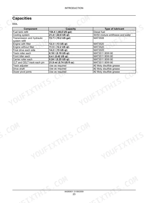
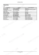
| Fuel tank refill | 154.4 l (40.8 US gal) | p. 27 |
| Cooling system | 21.4 l (22.6 US qt) | p. 27 |
| Transmission and hydraulic system refill | 72.7 l (19.2 US gal), MAT3508 | p. 27 |
| Engine with filter | 12.3 l (13 US qt), MAT3520 | p. 27 |
| Final drive, each side | 14.2 l (15 US qt), MAT3505 | p. 27 |
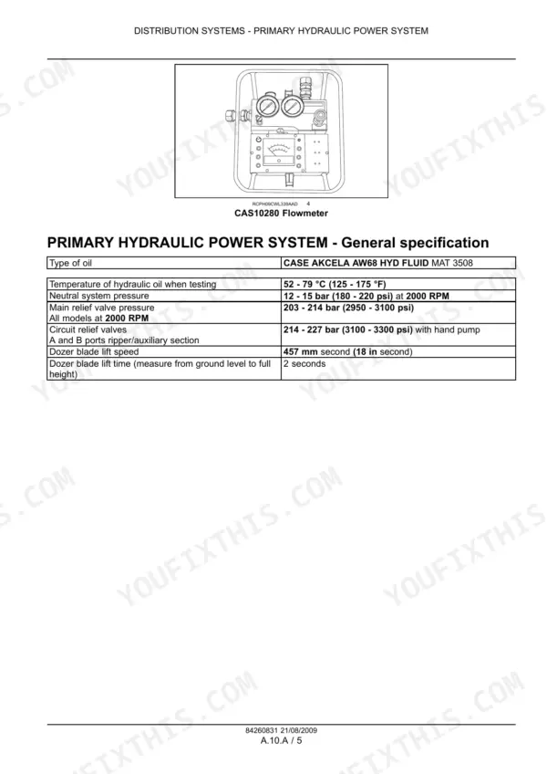
| Hydraulic oil | CASE AKCELA AW68 HYD FLUID MAT 3508 | p. 35 |
| Main relief valve pressure | 203 - 214 bar (2950 - 3100 psi) at 2000 RPM | p. 35 |
| Neutral system pressure | 12 - 15 bar (180 - 220 psi) at 2000 RPM | p. 35 |
| Circuit relief valves (ripper/auxiliary) | 214 - 227 bar (3100 - 3300 psi) | p. 35 |
| Dozer blade lift time | 2 seconds | p. 35 |
| Hydraulic pump output | 72 l at 207 bar at 2000 RPM (19 US gpm at 3000 psi) | p. 37 |
| Electrical system | 12 volt negative ground | p. 126 |
| Reverse ratio switch | 80, 100, 115, 130 per cent of forward speed | p. 759 |
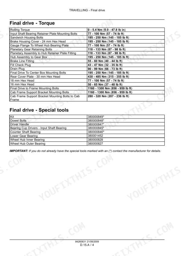
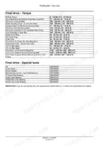
| Final drive to frame mounting bolts | 1160 - 1300 Nm (856 - 959 lb ft) | p. 854 |
| Final drive temperature after test | less than 71 °C (160 °F) | p. 863 |
| Track master link bolts | 305 - 335 Nm (225 - 247 lb ft), Loctite 242 | p. 937 |
| Standard link shoe bolts | 257 - 312 Nm (190 - 230 lb ft) | p. 937 |
Case 650L Common Problems This Manual Covers
Crawler will not move and the display shows 4622, no CAN communication with engine controller
Check fuse F8 in Connector R8 first (page 346). Write down every code, its occurrences and the engine hours, then clear them. Drive above 50% of the transmission speed range. If the code returns, check for an open circuit between Engine Control Unit connector E4 and main drivetrain controller connector R4. Also look for connectors that are not fully mated, bent pins and broken wires.
Manual Section: Fault Codes: Drivetrain Controller (DTC) p. 346Code 3028 oil pressure too low on the engine controller
Before you pull any sensor, check the engine oil type and level (page 416). The capacity with a filter change is 12.3 l (13 US qt) of MAT3520 (page 27). For step 2, disconnect the engine oil temp/pressure sending unit connector and turn the ignition ON. You should read 5 V at pin 3. If you do not, work back through the connector and wiring.
Manual Section: Fault Codes: Engine Controller (EDC) p. 416Final drive running hot after work
Run the final drive preliminary test on page 863. Drive at 50% speed for 2 minutes, stop, apply the parking brakes and check the final drive with a thermal gun. It should read less than 71 °C (160 °F). A higher reading points to a bearing that is too tight or a misassembled park brake. Reassembly torques are on page 854, including 195 - 250 Nm (145 - 185 lb ft) on the sandwich housing bolts.
Manual Section: Final Drive p. 863Blade lifts slowly or the hydraulics feel weak
Time the blade first: from ground level to full height should take 2 seconds (page 35). Then run the pump flow test with the oil at least 52 °C (125 °F). Read flow at 2000 r/min with the Flowmeter load valve fully open (page 91). Close the valve to 138 bar (2000 psi) and read again (page 92). Compare both readings to the rated 72 l at 207 bar at 2000 RPM (page 37) to work out pump efficiency.
Manual Section: Primary Hydraulic Power System p. 35Frequently Asked Questions
How do I read and clear fault codes on a Case 650L dozer?
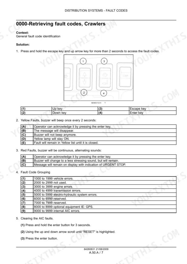
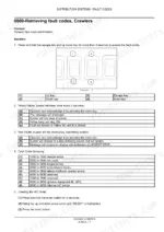
Press and hold the escape key and the up arrow key for more than 2 seconds to bring up the fault codes (page 237). A yellow fault beeps every 2 seconds and you acknowledge it with the enter key, but the yellow lamp stays on. A red fault holds a continuous buzzer and shows URGENT STOP. Codes are grouped by range: 1000-1999 vehicle, 3000-3999 engine, 4000-4999 transmission, 5000-5999 electro-hydraulic and 9000-9999 internal AIC. To clear AIC faults, hold enter for 3 seconds, scroll to RESET and press enter. That reset is for the AIC faults only. p. 237
What oil and how much goes in the Case 650L hydraulic system and final drives?
The transmission and hydraulic system share one refill of 72.7 l (19.2 US gal) of MAT3508 (page 27). Page 35 names that fluid as CASE AKCELA AW68 HYD FLUID MAT 3508. Each final drive takes 14.2 l (15 US qt) of MAT3505. The same capacities table lists 12.3 l (13 US qt) of MAT3520 for the engine with a filter change, and 11.5 l (12.2 US qt) without one. p. 27
What is the main relief pressure on a Case 650L?
Main relief is 203 - 214 bar (2950 - 3100 psi) at 2000 RPM (page 35). Get the oil up to 52 - 79 °C (125 - 175 °F) before you trust any gauge reading. Neutral system pressure should be 12 - 15 bar (180 - 220 psi) at 2000 RPM. The circuit relief valves at the A and B ports of the ripper/auxiliary section are set at 214 - 227 bar (3100 - 3300 psi) with a hand pump. From ground level, the blade should reach full height in 2 seconds. p. 35
What are the track master link bolt torques on a Case 650L?
Master link bolts on the steel track go to 305 - 335 Nm (225 - 247 lb ft) with Loctite 242 on the threads (page 937). Standard link shoe bolts are 257 - 312 Nm (190 - 230 lb ft). p. 937
Where are the wiring diagrams for a Case 650L?
Wiring harness schematic frames 01 to 27 run one per page from page 180 to page 206. They cover charging, cranking and cold start, power relays, the fuse and relay block, the drive train controller, pumps and motors, the F-N-R joystick and the engine control unit. Page 1227 is the fold-out 650L crawler electrical schematic with the wire color legend, schematic part number 84271238. Engine electrical schematics are not in this book. It refers you to the separate engine repair manual for those. p. 180










Reviews
There are no reviews yet.