
Part of the Case Repair Manuals.
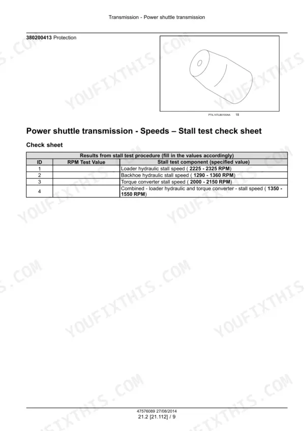
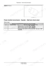
The Carraro TLB1 power shuttle gets two chapters. The first covers the specification, the stall test and check sheet, supply pump flow and relief pressure, and the 2WD and 4WD pressure tests. The second covers the external controls, the internals and the torque converter. Regulated clutch pressure is 1103 - 1303 kPa (160 - 189 psi) at 900 - 2200 RPM, on page 231.
The rest of the 570T is covered too. That includes the mechanical S8000 engine with its Bosch VE pump, both axles, brakes, loader and backhoe hydraulics, Danfoss steering, cab climate and electrical schematic sheets 01 to 18. The book is part number 47576089, printed June 2014. The stall test check sheet is on page 236 and the hydraulic schematic is on page 638.
What's Inside This Case 570T Manual
| System | Pages | Key Topics |
|---|---|---|
| Introduction | 1-32 | Safety Rules, Basic Instructions, Fuse and Relay Locations, Shop and Assembly, Minimum Tightening Torques for Normal Assembly, Standard Torque Data for Hydraulics, Abbreviations, Capacities |
| Engine: Block, Head and Crankshaft | 33-123 | S8000 Engine Specification and Tightening Torques, Sealants, Special Tools, Crankcase Specification, Static Description, Engine Remove and Install, Engine Troubleshooting, Pan and Covers, Valve Drive and Gears, Cylinder Heads, Connecting Rods and Pistons, Crankshaft and Flywheel |
| Engine: Fuel, Air, Cooling and Lubrication | 124-222 | Pump Drives, Fuel Tanks, Lift Pump and Lines, Fuel Injection System and Injection Pump Timing, Throttle Linkage, Turbocharger and Lines, Intake and Exhaust Manifolds and Muffler, Engine Cooling System, Engine Lubrication System, Aftercooler |
| Power Shuttle Transmission | 223-333 | Mechanical Transmission Lubrication System, Carraro TLB1 Power Shuttle Transmission Specification, Stall Test and Check Sheet, Supply Pump Flow and Relief Pressure Test, Transmission Remove and Install, 2WD and 4WD Pressure Tests, Troubleshooting |
| Transmission Controls, Internals and Torque Converter | 334-428 | Power Shuttle Transmission External Controls, Internal Components Disassembly and Assembly, Torque Converter |
| Front Axle System | 429-520 | Powered Front Axle Specification, Front Bevel Gear Set and Differential, Final Drive Hub, Steering Knuckles and Shafts, Non-Powered Front Axle, Front Axle Troubleshooting |
| Rear Axle System | 521-598 | Powered Rear Axle Specification and Torque Values, Rear Bevel Gear Set and Differential, Final Drive Hub and Shafts, Rear Axle Troubleshooting |
| Brakes and Controls | 599-628 | Hydraulic Service Brakes Specification, Brake Disks, Parking Brake or Parking Lock |
| Hydraulic Systems, Pump and Main Control Valve | 629-689 | Cylinder Specification and Working Pressure, Hydraulic Schematic, Steering Relief Valve Pressure Check, Pump Flow Test, Main System Pressure Test, Loader and Backhoe Circuit Testing, Reservoir, Cooler and Filters, Fixed Displacement Pump, Main Control Valve |
| Front Loader Hydraulics | 690-723 | Front Loader Hydraulic System Control Valve, Loader Arm Hydraulic System, Loader Bucket Hydraulic System Cylinders |
| Backhoe Hydraulics | 724-773 | Excavator and Backhoe Hydraulic Controls and Valve, Boom, Dipper, Backhoe Bucket and Swing Arm Hydraulic Systems and Cylinders |
| Hydraulic Systems Generic Sub-Group | 774-798 | Slew and Lift Cylinder Disassembly, Inspection and Assembly, Internal Leakage Check Points, Cylinder Troubleshooting for Rod Seal Leakage, Internal Leakage, Scored Tube, Bent Piston Rod and Plating Defects |
| Frames and Ballasting | 799-808 | Stabilizers |
| Steering | 809-854 | Steering Control, Danfoss Steering Unit Specification and Hydraulic Connection Torques, Hydraulic Control Components, Steering Relief Valve, Steering Cylinders and Tightening Torques |
| Wheels | 855-874 | Front Wheels, Rear Wheels, Tire Sizes, Inflating Pressures and Wheel Nut Torques |
| Cab Climate Control | 875-916 | Heating, Air Conditioning Specification, Evacuation and Recharging, Compressor, Condenser and Evaporator |
| Electrical: Harnesses and Component Diagrams | 917-1092 | Harness and Connector List, Component Diagrams 00 to 40 |
| Electrical: Schematic Sheets, Starting, Alternator and Wiper | 1093-1156 | Electrical Schematic Sheets 01 to 18 for Charging, Starting, Grounding, Engine Control, Lighting, Instrument Cluster and HVAC Circuits, Component Identification, Engine Starting System, Alternator, Wiper and Washer System |
| Front Loader and Bucket | 1157-1172 | Loader Arm, Loader Bucket |
| Booms, Dippers and Buckets | 1173-1198 | Boom Pivoting Support, Boom, Dipper Arm |
| Platform, Cab, Bodywork and Decals | 1199-1235 | Cab, Cab Doors and Hatches, Cab Glazing, Engine Hood and Panels |
| Special Tool Index | 1236-1243 | Index of Special Tools by Part Number |
Quick Reference Specifications
| Specification | Value | Page |
|---|---|---|
| Engine | S8000, 4 cylinder turbo charged and after cool diesel | p. 47 |
| Rated power (570T) | 63 kW (86 Hp) | p. 231 |
| Injection pump | BOSCH VE4/12F1100LV1693, firing order 1-3-4-2 | p. 140 |
| Injector pressure setting | 260 - 268 Kg/cm² (3698 - 3812 psi) | p. 140 |
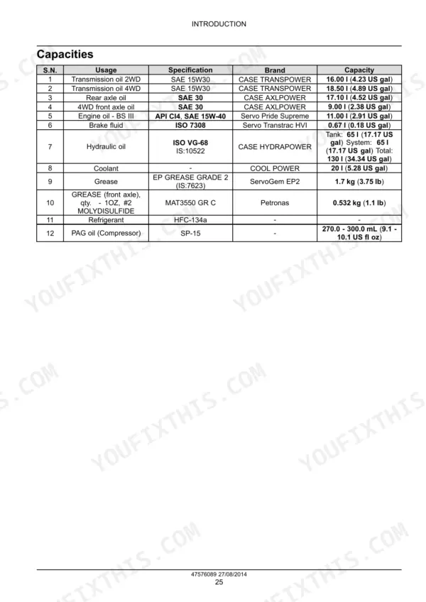
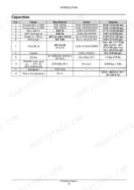
| Engine oil | API CI4, SAE 15W-40, 11.00 l (2.91 US gal) | p. 30 |
| Coolant | 20 l (5.28 US gal) | p. 30 |
| Transmission oil 2WD / 4WD | SAE 15W30, 16.00 l (4.23 US gal) / 18.50 l (4.89 US gal) | p. 30 |
| Rear axle oil | SAE 30, 17.10 l (4.52 US gal) | p. 30 |
| Hydraulic oil | ISO VG-68, tank 65 l (17.17 US gal), total 130 l (34.34 US gal) | p. 30 |
| Transmission | CARRARO TLB1 power shuttle, 4 forward and 4 reverse | p. 231 |
| Torque converter stall speed | 2000 - 2150 RPM | p. 236 |
| Cylinder working pressure | 210 bar (3045 psi) | p. 632 |
| Steering relief pressure check | 140 - 145 bar (2030 - 2102 psi) | p. 641 |
| Steering unit | DANFOSS PN 1119195, relief 140 bar (2030 psi) | p. 818 |
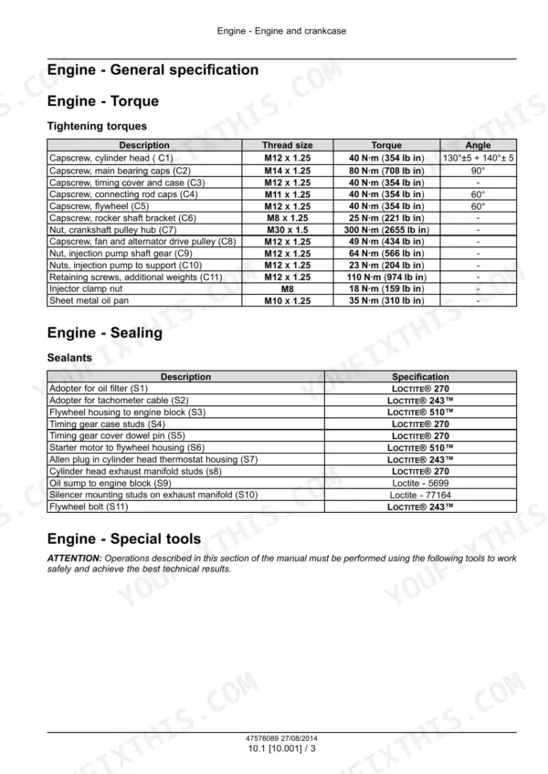
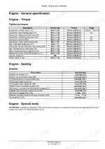
| Cylinder head capscrews | 40 N·m (354 lb in) + 130°±5 + 140°±5 | p. 36 |
| Wheel nuts front / rear | 196 N·m (145 lb ft) / 490 N·m (361 lb ft) | p. 870 |
Case 570T Common Problems This Manual Covers
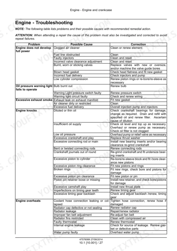
Engine does not develop full power
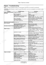
Check the causes listed on page 60: clogged air cleaner, obstructed fuel line, faulty injectors, wrong valve clearance, burnt/worn/sticking valves, blown head gasket, incorrect fuel delivery and low compression. Injector pressure setting is 260 - 268 Kg/cm² (3698 - 3812 psi), on page 140.
Manual Section: Engine: Block, Head and Crankshaft - Engine troubleshooting p. 60Engine overheats
Check the causes listed on page 60: a leaking or collapsed coolant hose, defective radiator cap, radiator leakage, wrong fan belt adjustment, restricted radiator fins, faulty thermostat, internal engine leakage and a faulty water pump. Coolant capacity is 20 l (5.28 US gal), on page 30.
Manual Section: Engine: Block, Head and Crankshaft - Engine troubleshooting p. 60Machine does not move in either direction
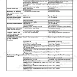
Check the causes listed on page 330: faulty supply to the solenoid valves, damaged solenoids, jammed or broken distributor spool or springs, low transmission pressure, worn clutch discs, damaged synchronisers and broken gears, shafts or bearings. Regulated clutch pressure is on page 231.
Manual Section: Power Shuttle Transmission - Troubleshooting p. 330Hydraulic cylinder rod seal leakage or internal leakage
Check the causes of rod seal leakage listed on page 795: seal wear, a scored rod, weld arcing, a wrongly assembled seal, a bent rod and high oil temperature. Internal leakage causes include a scored or rusted tube ID, external damage, air in the circuit and a damaged piston seal. For a damaged piston seal, replace the complete seal kit. Cylinder working pressure is 210 bar (3045 psi), on page 632.
Manual Section: Hydraulic Systems Generic Sub-group - Cylinder troubleshooting p. 795Frequently Asked Questions
What are the wheel nut torques on a Case 570T?
Front wheel nuts take 196 N·m (145 lb ft) and rear nuts take 490 N·m (361 lb ft), on page 870. Check them every 10 h when the machine is new or after a wheel has been removed. Standard tire sizes are on the same page: 2WD 9.00-16 front and 16.9-28 rear, 4WD 12.5-18 front. p. 870
What oil and how much goes in the Case 570T transmission, axles and hydraulic system?
Page 30 lists them. The 2WD transmission takes SAE 15W30 CASE TRANSPOWER, 16.00 l (4.23 US gal), and 4WD takes 18.50 l (4.89 US gal). The rear axle takes SAE 30 CASE AXLPOWER, 17.10 l (4.52 US gal). The 4WD front axle takes 9.00 l (2.38 US gal). Hydraulic oil is ISO VG-68 CASE HYDRAPOWER: 65 l (17.17 US gal) in the tank and 130 l (34.34 US gal) in total. Engine oil is SAE 15W-40, API CI4, 11.00 l (2.91 US gal). p. 30
What are the cylinder head bolt torques on the Case 570T engine?
The M12 X 1.25 head capscrews go to 40 N·m (354 lb in), then 130°±5, then 140°±5, on page 36. Main bearing caps are 80 N·m (708 lb in) + 90°. Rod caps and flywheel are 40 N·m (354 lb in) + 60°. The M30 X 1.5 crankshaft pulley hub nut is 300 N·m (2655 lb in). p. 36
How do I check the steering and main hydraulic pressure on a Case 570T?
For steering, bring the oil to 50 °C (122.0 °F). Fit a gauge of at least 250 bar (3625.0 psi) on the CF port in the pump. Run full throttle with the steering held at full lock. You should see 140 - 145 bar (2030 - 2102 psi). If not, adjust the relief valve in the steering unit (page 641). For main pressure, remove the PLUG 1/4" BSP from the 2-spool valve and fit a sensor rated for at least 450 bar (6526 psi). Then hold the loader lift or stabilizer lever at full throttle (page 649). p. 641
Where are the wiring diagrams for a Case 570T?
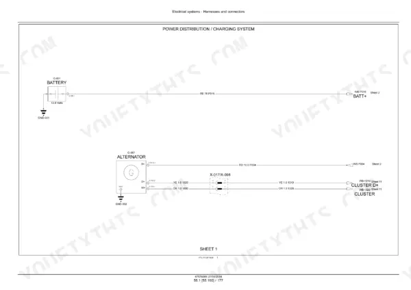
Electrical schematic sheets 01 to 18 are on pages 1093 to 1128, as listed on page 919. They cover power distribution and charging, starting, grounding, engine control, drives, hydraulics, lighting, wiper, instrument cluster, hazard, accessories, cab fan, audio, HVAC, mobile charger and dome light. The harness and connector list and component diagrams 00 to 40 come before them in the same section. p. 919









Reviews
There are no reviews yet.