

Part of the Case Repair Manuals.
The loader is parked with the bucket down and a fault code on the cluster. This is the Case service manual for the 21F, 121F, 221F and 321F Tier 4B (final) compact wheel loaders. It is part number 47829079B, 2nd edition, May 2015. It covers the 121F XT, 121F ZB, 21F XT, 21F ZB, 221F HS, 221F STD, 321F HS and 321F STD.
This book gives you the real figures for the axles, travel pump, loader valve, steering, brakes and quick coupler. It also has the harness sheets and fault codes from 2741 to 4920. The engine chapter only covers engine and fuel tank remove and install.
What's Inside This Case 21F, 121F, 221F, 321F Manual
| System | Pages | Key Topics |
|---|---|---|
| Introduction | 1-44 | Safety Rules, Basic Instructions for Shop and Assembly, Bolt and Pipe Fitting Tightening Torques, Consumables and Capacities, Machine Orientation, Hydraulic Contamination, Maintenance Standards, Electrical Equipment Precautions, Product Identification |
| Engine | 45-80 | Engine Remove and Install, Fuel Tank Remove and Install |
| Transmission Controls and Creeper | 81-96 | Powershift Transmission External Controls and Inching Valve, Creeper and Creep Speed Valve |
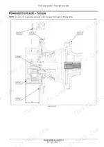
| Front Axle System | 97-200 | Powered Front Axle Specification for Axle Types 28.16 and 28.25, Dimensions, Torque, Remove and Install, Troubleshooting, Front Bevel Gear Set and Differential, Final Drive Hub, Steering Knuckles and Shafts |
| Rear Axle System | 201-366 | Powered Rear Axle 28.20 Specification, Torque, Transmission TB 172 and TB138.5 High Speed Motor, Rear Bevel Gear Set and Differential, Planetary and Final Drives, Final Drive Hub and Shafts |
| Brakes and Controls | 367-398 | Hydraulic Service Brakes, Parking Brake Adjustment, Front Axle Brake |
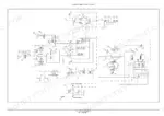
| Hydraulic Systems | 399-409 | Hydraulic Schematic Frames 01 and 02, Hydraulic System Troubleshooting |
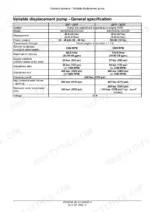
| Reservoir, Gear Pump and Variable Displacement Pump | 410-463 | Reservoir, Cooler and Filters, Gear Pump and Tandem Gear Pump, Variable Displacement Pump Specification, Adjustment and High Pressure Check |
| Main Control Valve, Pilot System and High Flow | 464-481 | Main Control Valve Specification and Exploded View, Pilot System, High Flow Valve |
| Hydraulic Travel System | 482-507 | Gear Shift Valve Specification, Dynamic Description, Check, Remove, Disassemble, Inspect and Assemble |
| Loader Arm, Bucket and Quick Coupler Hydraulics | 508-528 | Front Loader Arm Hydraulic System, Front Loader Bucket Hydraulic System Troubleshooting, Quick Coupler Valve |
| Frames and Ballasting | 529-538 | Counterweight Remove and Install |
| Steering | 539-574 | Steering Control, Steering Valve and Hydraulic Control Components, Steering Cylinders |
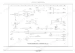
| Electrical System: Harness Layouts | 575-659 | Electrical Schematic Sheets 01 to 24 for the Main Cab, Cab Roof, Frame, Engine and Transmission, Arm, Battery and Auxiliary Harnesses, With Connector Tables |
| Electrical: Circuit Schematics, Connectors and Fuses | 660-731 | Wire Color Codes, Electrical Schematic Sheets 02 to 26 for Power Distribution, Engine Control, Hydraulic Controller, Lighting, Instrument Cluster, CAN Bus and HVAC Circuits, Wire Connectors, Fuse and Relay Box |
| Front Axle Control and Instruments | 732-747 | Front Axle Control System and Differential Lock Control Valve, Warning Indicators, Alarms and Instruments |
| Fault Codes: Transmission Controls (UCM) | 748-833 | Fault Code Index, UCM Codes 2741 to 2894 for Differential Lock, Forward, Reverse, Direction, Gear, Creep Speed and Inching Solenoids |
| Fault Codes: Engine Control Unit (ECU) 3007-3518 | 834-1000 | Sensors, Injectors, Crankshaft and Camshaft Signals, Rail Pressure, Fuel Metering Unit, Glow Plugs, Oil Pressure, EGR and DPF Inducement Codes |
| Fault Codes: Engine Control Unit (ECU) 3616-3978 | 1001-1165 | Torque Limitation, H-Bridge and Valve Position, Injector Power Stages, Turbine Sensors, Fuel Metering and Diesel Particulate Filter Codes |
| Fault Codes: Hydraulic Functions (UCM) | 1166-1260 | UCM Codes 4351 to 4920 for Quick Coupler, High Flow, 3rd Function, Ride Control, Return to Dig, Floating and Main Hydraulics Solenoids |
| Platform, Cab, Bodywork and Decals | 1261-1281 | Cab Remove and Install |
| Special Tool Index | 1282-1287 | Index of Special Tools |
Quick Reference Specifications
| Specification | Value | Page |
|---|---|---|
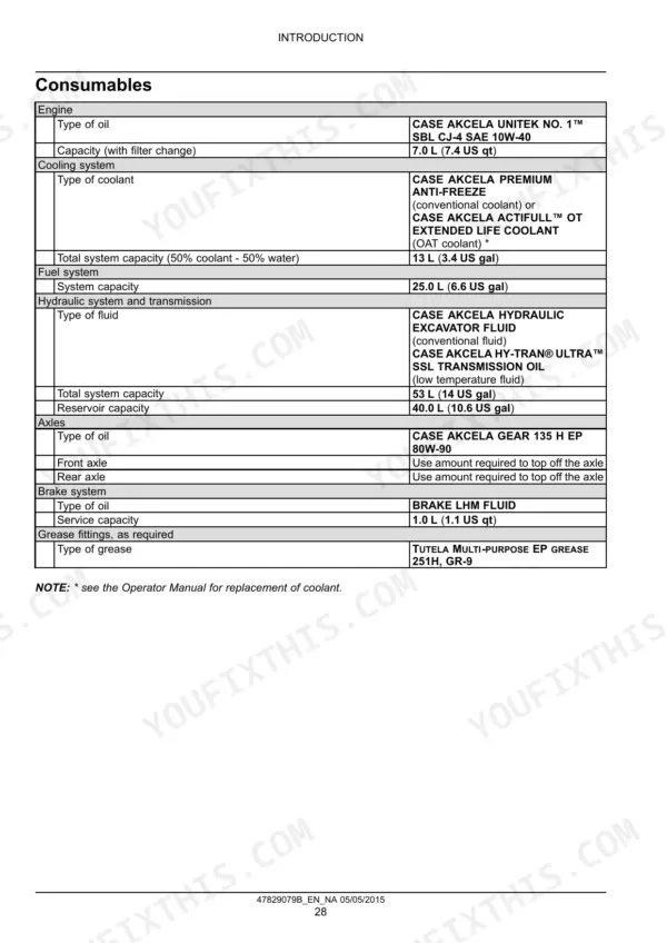
| Engine oil | CASE AKCELA UNITEK NO. 1 SBL CJ-4 SAE 10W-40, 7.0 L (7.4 US qt) with filter change | p. 33 |
| Cooling system | 13 L (3.4 US gal), 50% coolant - 50% water | p. 33 |
| Fuel system | 25.0 L (6.6 US gal) | p. 33 |
| Hydraulic system and transmission | total 53 L (14 US gal), reservoir 40.0 L (10.6 US gal) | p. 33 |
| Axle oil | CASE AKCELA GEAR 135 H EP 80W-90 | p. 33 |
| Brake fluid | BRAKE LHM FLUID, 1.0 L (1.1 US qt) | p. 33 |
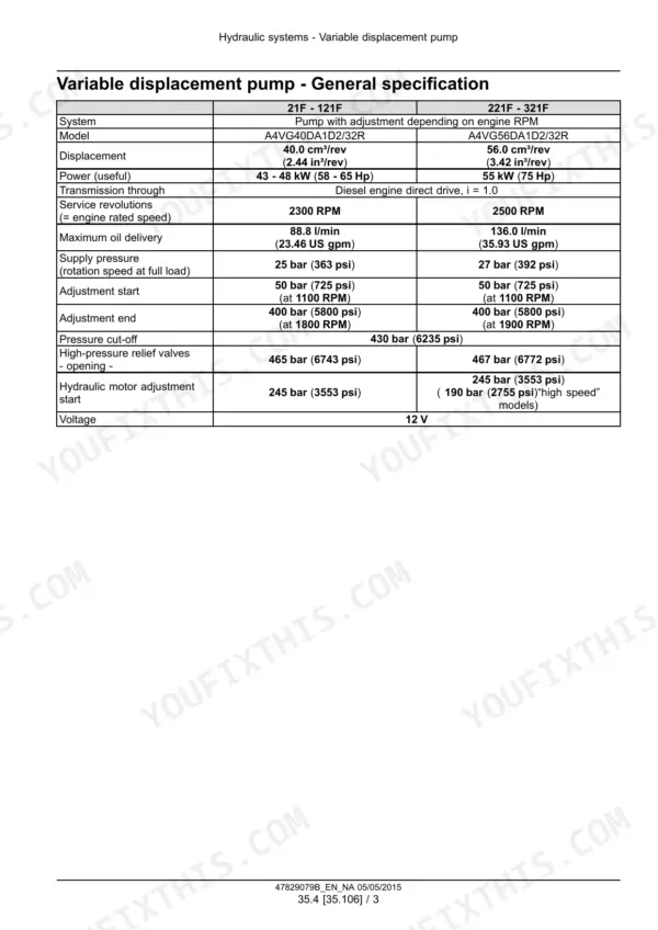
| Travel pump 21F - 121F | A4VG40DA1D2/32R, 40.0 cm³/rev (2.44 in³/rev) | p. 430 |
| Travel pump 221F - 321F | A4VG56DA1D2/32R, 56.0 cm³/rev (3.42 in³/rev) | p. 430 |
| Engine rated speed 21F - 121F / 221F - 321F | 2300 RPM / 2500 RPM | p. 430 |
| Travel pump pressure cut-off | 430 bar (6235 psi) | p. 430 |
| High-pressure relief valves 21F - 121F / 221F - 321F | 465 bar (6743 psi) / 467 bar (6772 psi) | p. 430 |
| Pump check oil temperature | 60 - 70 °C (140 - 158 °F) | p. 460 |
| Main control valve | 80 L/min (21.1 US gpm), nominal pressure 280 bar (4060 psi) | p. 466 |
| Main control valve plugs and valves | 42 N·m (31 lb ft) | p. 467 |
| Front axle 28.16 (21F - 121F) differential oil | 7.5 L (2.0 US gal) | p. 102 |
| Front axle 28.25 (221F - 321F) differential oil | 8 L (2.1 US gal) | p. 103 |
| Rear axle 28.20 (21F - 121F) transmission box | TB 172, oil 1.3 L (0.3 US gal) | p. 208 |
Case 21F, 121F, 221F, 321F Common Problems This Manual Covers
Machine does not move forward or back
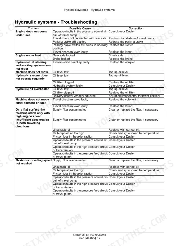
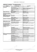
Check the two causes listed on page 408. One is a faulty travel direction valve, fixed by replacing the solenoid. The other is a faulty travel direction lever, fixed by replacing the lever. The UCM fault code section also covers the forward, reverse and direction solenoids.
Manual Section: Hydraulic Systems - hydraulic system troubleshooting p. 408Hydraulic oil running hot
Check the three causes listed on page 408: low oil level (top up), a clogged oil filter (replace it) and delivery control set wrong (adjust it for lower delivery). The Reservoir, Gear Pump and Variable Displacement Pump section covers the reservoir, cooler and filters.
Manual Section: Hydraulic Systems - hydraulic system troubleshooting p. 408Bucket slow to lift or dump, or weak lifting force
Check the causes listed on page 519 for slow dumping or lifting. They include a low pressure setting, low engine RPM, low pump delivery rate, and faulty kinematics in the control valve section. Internal leaks in the control valve section or cylinders and short spool travel are also listed. Weak lifting force points to a low pressure setting or internal leaks.
Manual Section: Loader Arm, Bucket and Quick Coupler Hydraulics - front loader bucket hydraulic system troubleshooting p. 519Steering is heavy and the loader keeps going straight while turning
Check the causes listed on page 116. They include a badly installed or defective axle, overload or wrong weight distribution, and a broken axle beam. Tires with different rolling radii are another cause, fixed by replacing a tire or adjusting pressures. Incorrect use of the product is also listed.
Manual Section: Front Axle System - troubleshooting p. 116Frequently Asked Questions
What oil and how much goes in the Case 21F, 121F, 221F and 321F engine, hydraulic system and brakes?
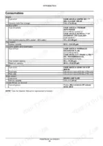
Page 33 lists every consumable. Engine oil is CASE AKCELA UNITEK NO. 1 SBL CJ-4 SAE 10W-40, 7.0 L (7.4 US qt) with a filter change. The hydraulic system and transmission take CASE AKCELA HYDRAULIC EXCAVATOR FLUID or CASE AKCELA HY-TRAN ULTRA SSL. Total system capacity is 53 L (14 US gal) and the reservoir holds 40.0 L (10.6 US gal). The brakes take BRAKE LHM FLUID, service capacity 1.0 L (1.1 US qt). The cooling system holds 13 L (3.4 US gal) of 50% coolant - 50% water. The axles take CASE AKCELA GEAR 135 H EP 80W-90, topped off. p. 33
What does fault code 3409 or 3146 mean on a Case 321F?
Both are ECU codes. Code 3409 (page 974) means engine speed is over 500 RPM and the oil pressure switch did not close. The book lists low engine oil level, a faulty lubrication system, an open signal wire, a faulty switch or a faulty ECU. One step is a resistance check from ECU connector X-078 pin 6 to switch connector pin 1, which should be less than 10 Ω. Code 3146 (page 891) means water detected in fuel. With the sensor unplugged and key ON, pin 1 to chassis ground should read less than 0.5 V. p. 974
What are the hydrostatic travel pump pressures on the Case 221F and 321F?
Page 430 lists the 221F - 321F pump as an A4VG56DA1D2/32R at 56.0 cm³/rev (3.42 in³/rev). It runs at 2500 RPM and delivers up to 136.0 l/min (35.93 US gpm). The high-pressure relief valves open at 467 bar (6772 psi), and pressure cut-off is 430 bar (6235 psi). Page 460 says to do any check and adjustment with hydraulic oil at about 60 - 70 °C (140 - 158 °F). p. 430
How do I check the travel pump zero-setting on a Case 121F?
Page 460 covers the mechanical zero-setting check. Put a gauge that reads up to 600 bar (8700 psi) on both PHD measuring points. Secure the machine so it cannot move and leave the travel lever at idle. Loosen safety nut (A). Turn centring rod (B) with a 5 mm (0.197 in) Allen wrench until MA and MB read the same supply pressure. Then lock the safety nut. p. 460
Where are the wiring diagrams for the Case 21F to 321F?
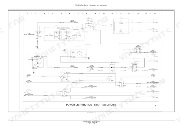
Harness layout sheets 01 to 24 start on page 576. The circuit schematics are on pages 665 to 718. They cover power distribution and starting, the ECU, the hydraulic controller and cab joystick, lighting, the CAN bus, HVAC and more. Page 660 introduces the section, which also has the wire color codes, connectors and the fuse and relay box. Page 740 explains the UCM, ADIC and ECU and the ISO 11783 diagnostic connector for the EST. p. 660








Reviews
There are no reviews yet.