


Part of the Case Repair Manuals.
All 849 pages of this Case 435, 445CT, 445 Repair Manual (OEM Bur 6-75491) exist for one reason: getting your skid steer or compact track loader back to factory spec. Inside you get full hydraulic schematics covering the primary, secondary, and high-flow power systems, complete wiring diagrams for the electrical and lighting circuits, and step-by-step procedures running from the Power Train through Working Arm and Tools and Couplers sections. The hydraulic lift circuit leakage threshold is spelled out at 3.8 L/min, and main relief pressure at 10 GPM is set to 21290 kPa, the kind of number you won't find guessing with a pressure gauge. Your hydraulic pump displacement runs 36cc across all three models. No more chasing a leaking arm cylinder with a parts-counter guess. This bookmarked PDF opens on your phone or tablet, so you can search by keyword and have the spec pulled up before the machine's even shut down.
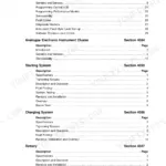
What's Inside This Case 435, 445CT, 445 Repair Manual
| System | Pages | Key Topics |
|---|---|---|
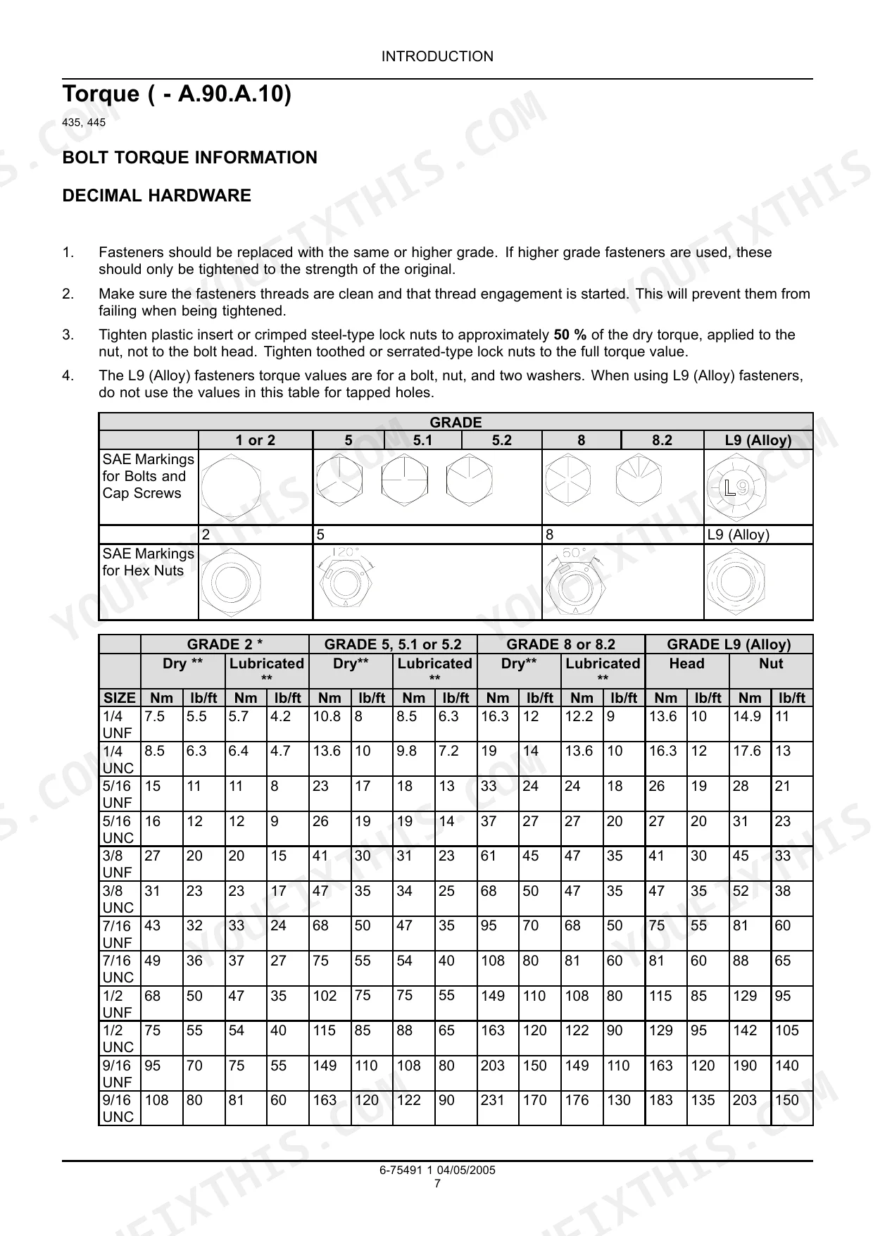
| Introduction | 4-19 | Basic Instructions, Torque, Consumables, Conversion Factors |
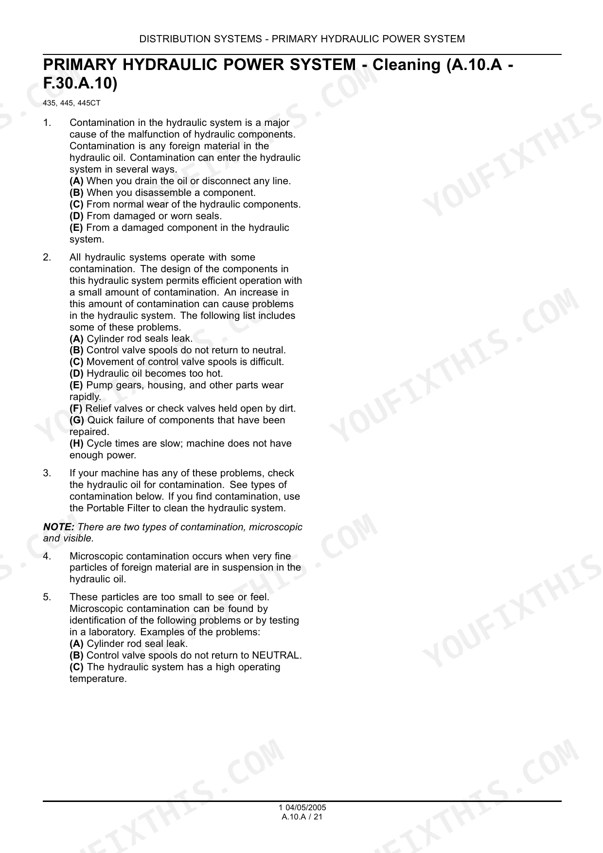
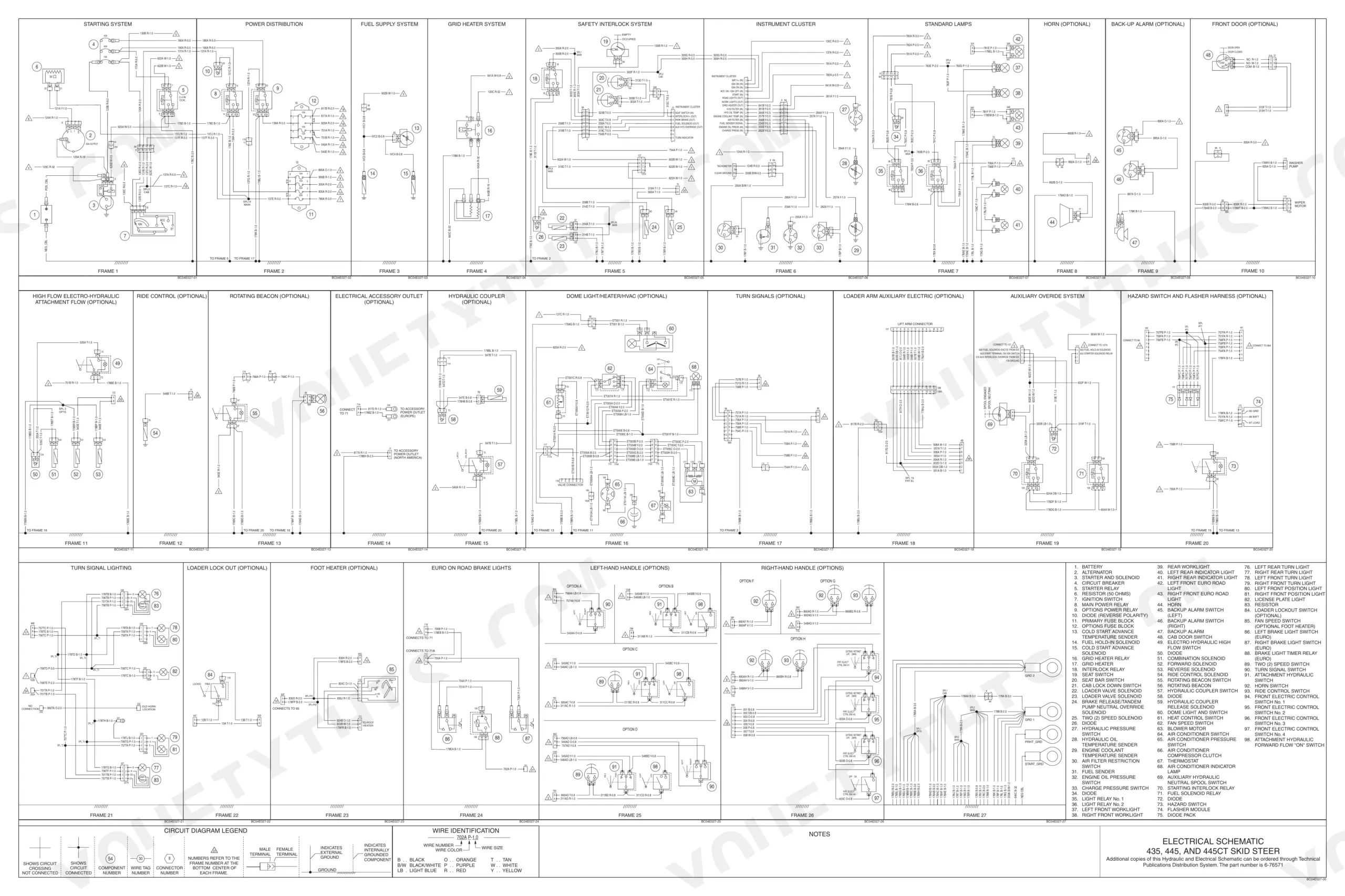
| Distribution Systems | 20-253 | Primary Hydraulic Power System, Secondary Hydraulic Power System, High-Flow Hydraulic Power System, Electrical Power System, Lighting System, Hydraulic Command System |
| Power Production | 254-351 | Engine, Fuel and Injection System, Air Intake System, Engine Coolant System, Lubrication System, Starting System |
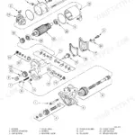
| Power Train | 352-481 | Power Coupling Fixed Coupling, Transmission Hydrostatic, Drive Plate, Motor, Pump, Relief Valve |
| Travelling | 482-577 | Front Axle, Rear Axle, Parking Brake Hydraulic, Wheels and Tracks, Final Drive, Steering Mechanical |
| Body and Structure | 578-715 | User Controls and Seat, User Platform, Environment Control Heating System, Environment Control Air-Conditioning System, Safety Security Accessories Safety |
| Working Arm | 716-805 | Single Arm Lift, Single Arm Tool Attachment Tilt, Accumulator, Control Valve, Cylinder, Relief Valve |
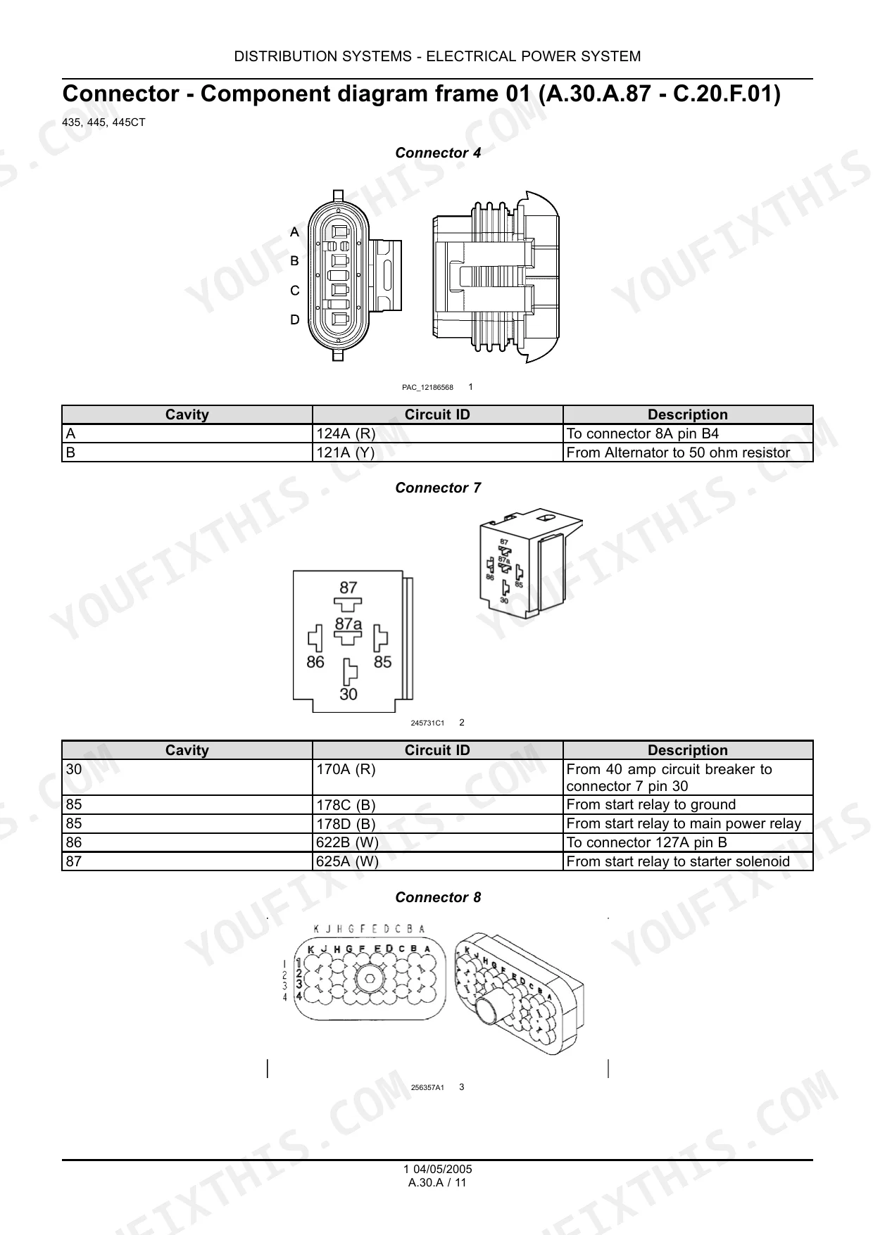
| Tools and Couplers | 806-847 | Carrying Unarticulated Tools, Coupling Hydraulic Coupling, Coupling Mechanical Coupling, Tool Bucket, Command Valve Solenoid, Connector |
| Elecrical and Hydraulic Schematic | 848-849 | - |
Quick Reference Specifications
| Specification | Value | Page |
|---|---|---|
| All Models | ||
| Hydraulic lift circuits leakage threshold | 3.8 L/min (one gpm) | p. 753 |
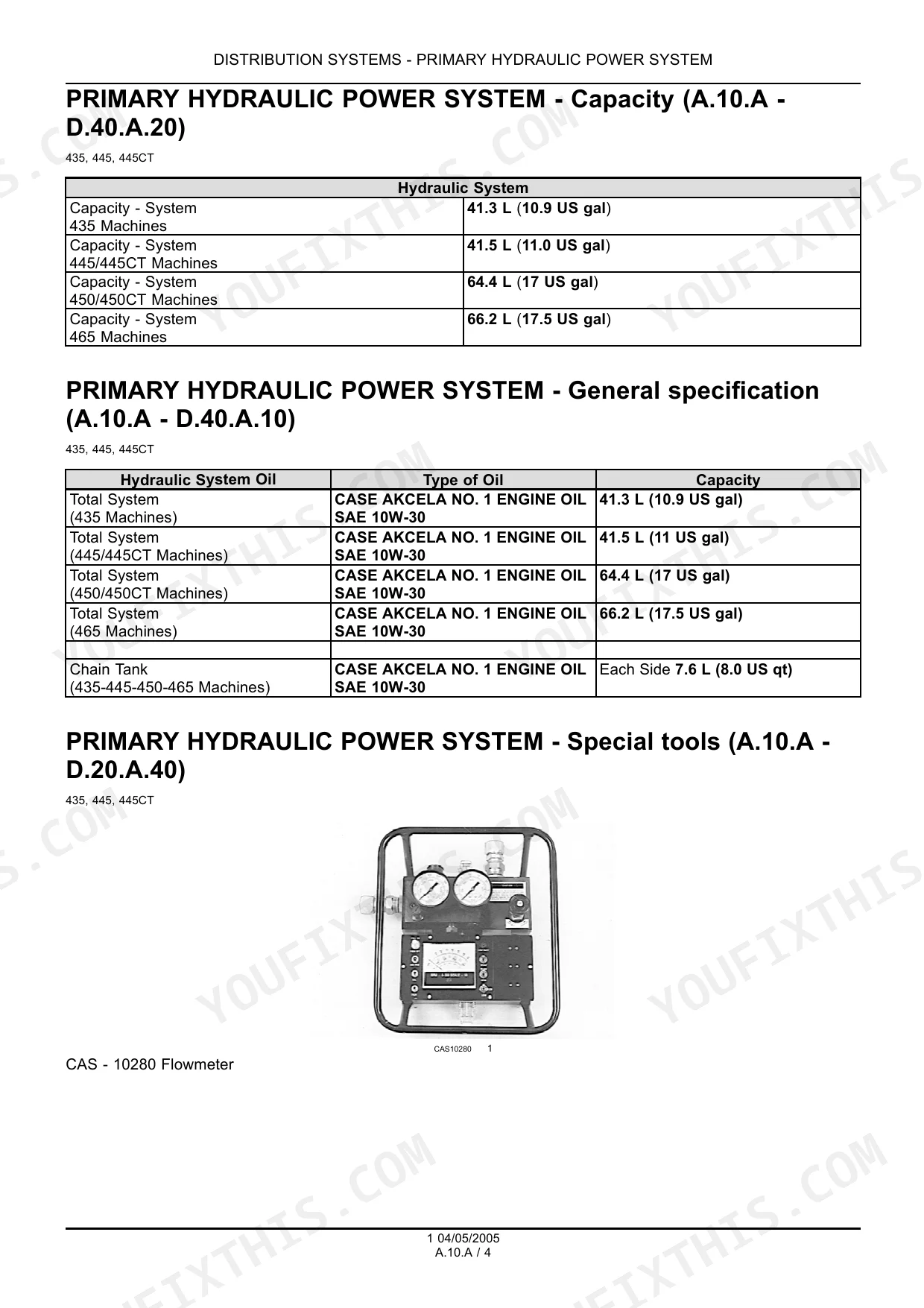
| Main Relief Pressure at 10 gpm | 21290 kPa | p. 27 |
| Oil Filter Bypass Pressure | 345 kPa | p. 29 |
| Engine Coolant System Capacity | 17 L | p. 302 |
| Engine Starter Number of Teeth | 13 | p. 318 |
| Hydrostatic Pump Charge Pressure | 2482 kPa | p. 374 |
| Front Axle Nuts Torque | 223 - 265 Nm | p. 486 |
| Loader Lift Cylinder Piston Bolt Torque | 365 - 460 Nm | p. 722 |
| 435, 445, 445CT | ||
| Hydraulic Pump Displacement | 36cc | p. 28 |
| 435 | ||
| Engine Oil Capacity (435 Machines) | 8.0 L | p. 312 |
| 445, 445CT | ||
| Engine Oil Capacity (445, 445CT Machines) | 12.0 L | p. 312 |
| 445CT | ||
| Parking Brake Capacity (445CT) | 8000 Nm | p. 514 |
Case 435, 445CT, 445 Common Problems This Manual Covers
Control levers locked out unexpectedly when safety locks engage, won't release
Inspect the parking brake button assembly described in the safety accessories section starting page 578. A sticking switch can mimic a mechanical lockout, so cycle the button several times and check for 12V at the spool lock solenoid connector before tearing into the lever linkage or condemning the lock mechanism.
Manual Section: Safety Security Accessories Safety p. 578Hydrostatic drive sluggish or one track drags under load, low charge pressure reading
Run the hydrostatic troubleshooting procedure. Tee a gauge into the charge pressure port and confirm a reading near 2482 kPa, the spec listed on page 374; anything noticeably lower points to a worn charge pump or excessive case drain leakage. Replace the charge relief valve if pressure won't climb after the unit reaches operating temperature.
Manual Section: Transmission HydrostaticWorking arm bounces or drifts down slowly after being raised and parked
Check accumulator condition under the Working Arm system near page 723, where maximum operating pressure is rated at 20700 kPa. A low nitrogen pre-charge lets the arm settle under its own weight after shutdown. Recharge or replace the accumulator if the arm won't hold its raised position with the engine off.
Manual Section: Working Arm p. 723Bucket lift weak or slow with hydraulic pump pressure low warning displayed
Hook a gauge to the main relief test port and run the flow test at 10 gpm per the spec on page 27, where relief should hold at 21290 kPa. If pressure reads low, work through the cleaning procedure starting to rule out a clogged suction strainer before condemning the pump.
Manual Section: Primary Hydraulic Power System p. 27Frequently Asked Questions
What are the torque specs for the hydraulic pump mount on Case 445?
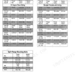
For Case 445 and 445CT machines, the bolts for the pump mounting plate should be tightened to a torque of 47 - 61 Nm (35 - 45 lb ft). This ensures the hydraulic pump is securely fastened to its housing. p. 356
What are the replacement specifications for Hydraulic pump fittings (JIC 90° and rubber line tees)?
For steel hydraulic fittings, the torque specifications vary by thread size and type. For example, a 5/16 - 24 thread size for a 37 Degree Flare Fitting requires 8 to 9 Newton metres (72 to 84 lb/in), while a 1-1/2 inch 1-7/8 - 12 thread size for a Straight Thread with O-ring requires 492 to 542 Newton metres (363 to 400 lb/ft). Always apply sealant/lubricant to male pipe threads, leaving the first two threads uncovered to prevent system contamination. p. 12
How do you fix case 435 hydraulic bucket or arm leaking oil continuously, cylinder won't hold position?
Check the lift circuit leakage spec on page 753 first; return flow above 3.8 L/min (one gpm) at the cylinder means seals are shot. Inspect JIC 90° fittings and rubber line tees for cracks or weeping, torque the lift cylinder piston bolt to 365-460 Nm per page 722, and replace the cylinder seal kit if leakage persists. p. 753
How do you fix auxiliary hydraulic lines not functioning even though fuses checked and appear good?
Check the wiring diagram to trace the fuel solenoid and auxiliary circuit. Verify the inline fuse is intact and confirm at least 12V reaches the solenoid connector with the key on. Clean and re-seat the ground terminal, then retest before replacing the solenoid itself.
Is this Case 435, 445CT, 445 Repair Manual a digital download?
Instant PDF download. You get the full 849-page searchable Repair Manual immediately after payment. Open it on your laptop, tablet, or phone right in the shop.
Can I print this manual?
The PDF is DRM-free. Print whatever sections you need to take out to the shop. Standard letter or A4 paper works.
Does this Case 435, 445CT, 445 manual include hydraulic schematics?
Included. Hydraulic system schematics cover all circuits, control valves, and component specifications for the Case 435, 445CT, 445.


Reviews
There are no reviews yet.