
Part of the Case Repair Manuals.
This 110-page J. I. Case Shop Manual (models 730, 830, 930, 1030) puts the entire tractor line's engine, transmission, and Case-O-Matic overhaul procedures in your hands. You get complete wiring diagrams for the electrical circuit and distributor timing, hydraulic schematics covering the rockshaft, control valves, and pump, and a full torque section that doesn't leave you guessing on cap screws. Inside you'll also find LP-Gas carburetor adjustment, diesel injection pump timing, and steering gear overhaul laid out step by step. Set the power steering pump cover cap screws to 35 ft.-lbs. and hold roller clearance under 0.0015 inch; on Series 930 and 1030, seat that oil seal with its inner edge flush to the bore. No more guessing which shim pack or bearing liner your particular series takes. Bookmarked by section, so you can jump straight from the front axle to the final drives without scrolling through 110 pages on your phone in the shop.
What's Inside This J. I. Case 730, 830, 930, 1030 Manual
| System | Pages | Key Topics |
|---|---|---|
| Service Data | General, Tune-Up, Sizes-Capacities-Clearances | |
| Cam Followers | Removal, Clearance, Resizing, Installation | |
| Camshaft | R&R, Gear, Bushings, Thrust Washer, Journals | |
| Connecting Rods & Bearings | Caps, Crankpin Diameter, Bearing Liners, Rod Side Play | |
| Crankshaft & Bearings | Main Bearings, Crankshaft End Play, Main Bearing Journal Out-Of-Round, Main Bearing Liners, Bronze Thrust Washers | |
| Crankshaft Seals | Front Oil Seal, Rear Oil Seal, Oil Cushion Clutch | |
| Counter-Balancer | Operation, Remove and Reinstall, Inspection, Overhaul | |
| Cylinder Heads | Head Gasket, Metal Fire Rings, Intake Manifold, Exhaust Manifold, Rocker Arm Cover, Retaining Cap Screws | |
| Cylinder Sleeves | Refinishing, Sleeve Bore, Sealing Rings, Removal, Reinstallation | |
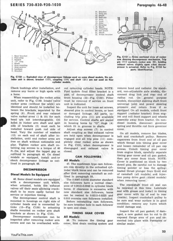
| Decompressor | Control Shaft, Links, Actuating Shafts, Set Screws, Trip Pins, Stop Screws | |
| Flywheel | Removal, Oil Seal Retainer, PTO Driving Sleeve, Oil Metering Plug, Wiggle Pin, Ring Gear | |
| Main Bearings | Crankshaft, Bronze Thrust Washers, Main Bearing Journal Diameter, Crankshaft End Play, Main Bearing Liners, Main Bearing Caps | |
| Oil Pan | Radius Rod, Torque Converter Housing, Seal Plate, Removal, Reinstallation | |
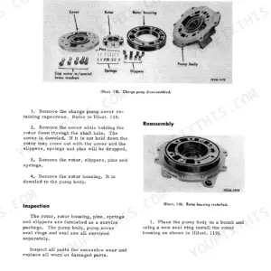
| Oil Pump | Relief Valve, Overhaul, Pump Gears, Idler Gear Shaft, Removal, Timing | |
| Piston & Rod Removal | Cylinder Heads, Oil Pan, Connecting Rod Bearing Caps, Engine Counter-Balancer | |
| Piston Pins & Bushings | Piston Pins, Snap Rings, Pin Bushing, Connecting Rod, Piloted Arbor, Oil Hole | |
| Pistons, Rings & Sleeves | Pistons, Compression Rings, Oil Control Ring, Piston Pins, Cylinder Sleeves, Piston Skirt Clearance | |
| Remove & Reinstall | Engine, Clutch, Cooling System, Oil Pan, Torque Converter Housing, Front Support | |
| Timing Gear Cover | Timing Pointer, Spring-Loaded Thrust Plunger, Crankshaft Front Oil Seal, Oil Pan Gasket, Dowel Pins | |
| Timing Gears | Crankshaft Gear, Camshaft Gear, Injection Pump Drive Gear, Timing Marks, Backlash, Camshaft Bushings | |
| Valves & Seats | Intake Valves, Exhaust Valves, Valve Seat Width, Stem Diameter, Valve Guides, Valve Springs, Valve Rotators | |
| Axle & Support | Steering Knuckles, Needle Bearings, Oil Seal, Axle Pivot Pins and Bushings, Pivot Pins, Bushing | |
| Adjustment | Worm Shaft End Play, Upper Spindle End Play, Sector Shaft End Play, Wheel Turning Angle, Starting Adjustment, Load Adjustment, Pressure Check | |
| Fuel Tank & Lines | Float-Type Fuel Gage, Safety Relief Valve, Fuel Lines, Fuel Filter | |
| Operation | LP-Gas Fuel Vaporization, Regulator Function, Control Valve Spools, Load Check Balls, Main Relief Valve, Flow Divider Valve | |
| Belt Pulley | 88-89 | Pulley Operating Rod, Adjusting Shim Pack, Drive Bevel Gear Backlash, Outer Shaft Nut, Inner Shaft, Pilot Bushing |
| Case-O-Matic Unit | Control Valve, Main Clutch, Tests & Adjustment, Torque Converter, Tractor Split, Trouble Shooting | |
| Chain, Final Drive | 81-82 | Drive Chains, Drive Sprockets, Driven Sprockets, Master Link |
| Cooling System | Radiator, Thermostat, Water Pump | |
| Diesel Fuel System | 39-45 | Bleeding, Filters and Lines, Injection Pump, Injector Nozzles, Powrcels, Timing |
| Differential | 83-84 | Differential Drive Gear, Final Drive Sprockets, Cross Shaft, Thrust Balls, Bearing Carriers, Bevel Ring Gear |
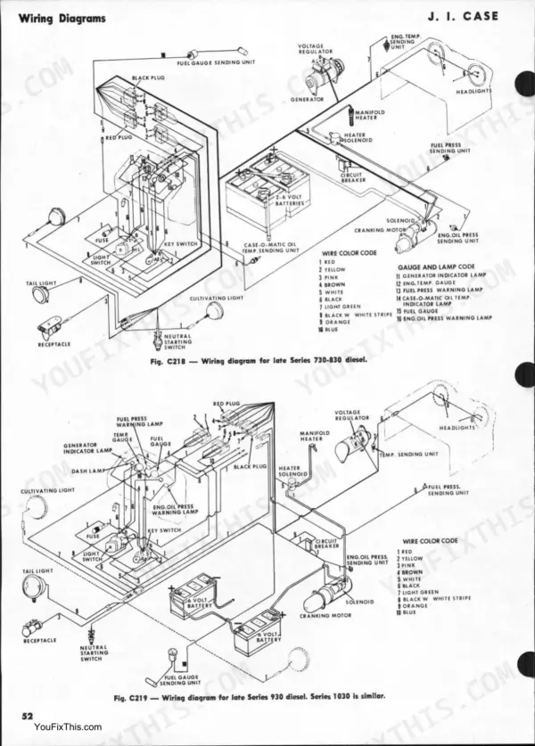
| Electrical System | 49-51 | Circuit Description, Distributor, Generator & Regulator, Timing |
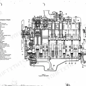
| Engine | 20-30 | |
| Final Drives | 81-87 | Final Drive Chains, Differential Drive Gear, Final Drive Sprockets, Rear Axle, Axle Housing, Differential Carrier Bearings, Bevel Gear Backlash, Bull Pinions |
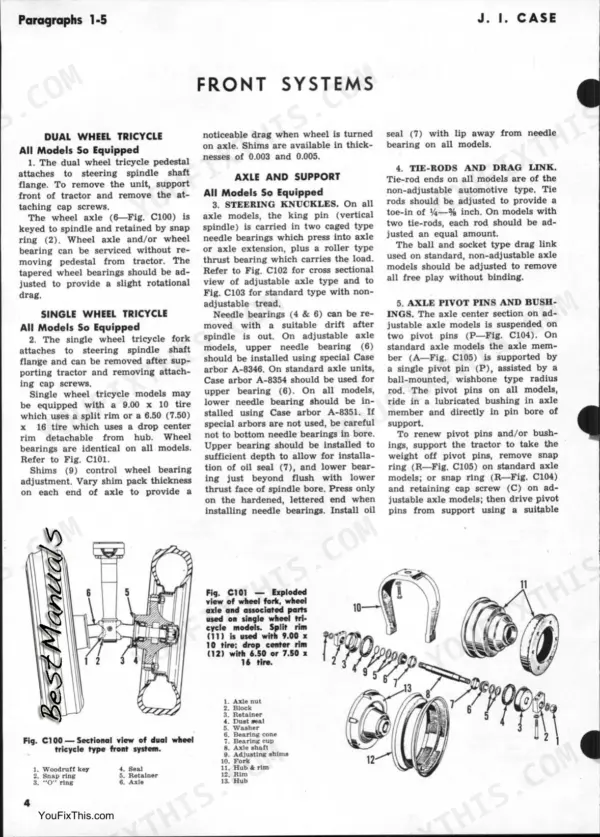
| Front System | 3-4 | Axle & Support, Dual Wheel Tricycle, Single Wheel Tricycle |
| Governor (Non-Diesel) | 46-47 | Recommended Speeds, Speed Adjustments, Linkage Adjustments, Governor Service, Governor Weights, Governor Lever, Governor Shaft, Governor Fingers |
| Hydraulic System | 97-110 | Adjustment, Control Valves, Cylinders, Fluid & Filter, Operation, Pump, Rockshaft & Linkage, Trouble Shooting |
| Lp-Gas System | 35-38 | Adjustment, Carburetor, Fuel Tank & Lines, Operation, Trouble Shooting |
| Power Take-Off | 90-95 | Clutch, Housing & Gears |
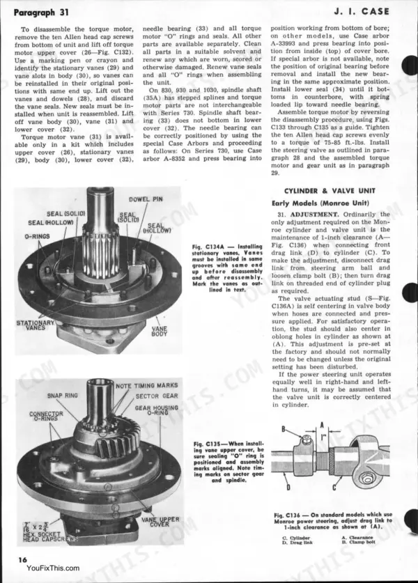
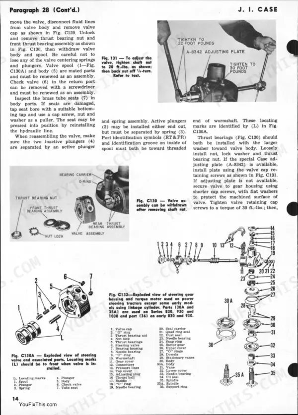
| Steering Gear | 4-9 | Spindle End Play, Worm Shaft End Play, Sector Shaft End Play, Worm & Sector Backlash, Wheel Turning Angle, Steering Gear Overhaul, Steering Valve |
| Transmission (Six-Speed) | 66-71 | Gears & Shafts, Shifter Assembly, Top Cover |
Quick Reference Specifications
| Specification | Value | Page |
|---|---|---|
| All Models | ||
| Power steering pump cover cap screws and nuts torque | 35 ft.-lbs. | p. 12 |
| Power steering pump roller clearance (max) | 0.0015 | p. 12 |
| Rod Bearings Running Clearance | 1.3-3.8 thousandths | p. 2 |
| Cylinder Head Stud Nuts Torque | 100 ft.-lbs. | p. 21 |
| early models | ||
| Hydraulic pump cap screws torque | 40-45 ft.-lbs. | p. 103 |
| late models | ||
| Hydraulic pump mounting cap screws torque | 35-40 ft.-lbs. | p. 103 |
| 730/830 | ||
| Crankcase Oil Capacity (with Filter) | 9 quarts | p. 2 |
| Cooling System Capacity | 7.5 gallons | p. 2 |
J. I. Case 730, 830, 930, 1030 Common Problems This Manual Covers
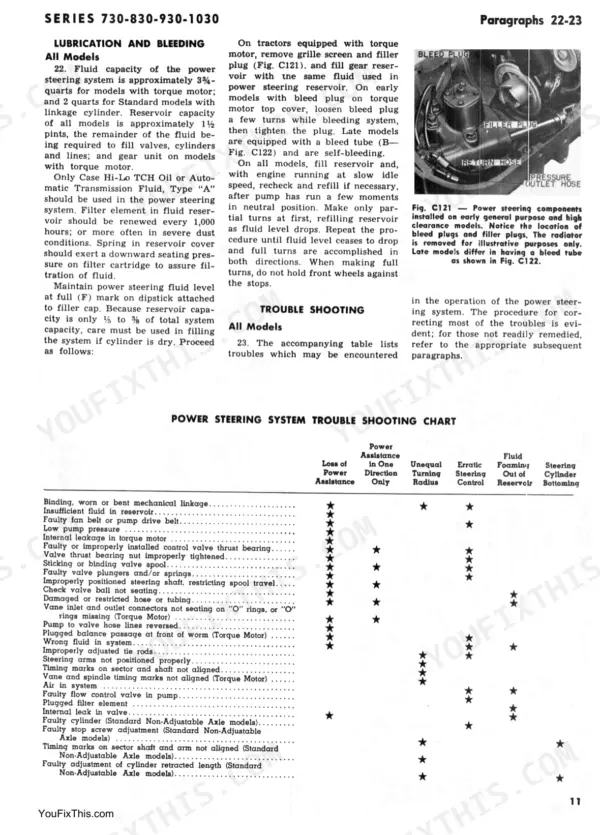
Case 1030 power steering wheel spins freely with no resistance or assist at low speed
Pull power steering pump per troubleshooting steps. Remove pump and check drive key at pump shaft for shearing or wear; a stripped key kills pump rotation instantly. Reinstall with new key, torque cover cap screws and nuts to 35 ft.-lbs. (page 12), then verify relief pressure reads 950-1100 psi (page 11) with engine at operating RPM.
Manual Section: Power Steering System Trouble ShootingPower steering fluid foams in the reservoir, steering effort surges up and down while driving
Check the power steering troubleshooting steps for foaming and erratic assist. Drain and refill reservoir with correct fluid, bleed air from lines, then test flow control valve spring; free length should measure 1.93 inches and compress to 0.82 inches under 8.5 lbs of load. Replace the spring if it's collapsed or fatigued.
Manual Section: Power Steering System Trouble ShootingRear axle howls or clunks under load, gradual loss of drive develops on one side
Split the rear axle housing and inspect the axle oil seal for hardening or lip wear. On 930 and 1030 models, seat the new seal with its inner edge flush with the seal bore (page 83). Check bearing carriers for scoring, repack with fresh gear lube, and replace worn bull pinions before reassembly to stop the noise.
Manual Section: Final Drives p. 83Three-point hydraulic lift arms drop slowly under a loaded implement or won't raise it
Check reservoir fluid level first; on 930 models it holds 14 U.S. quarts plus about 2 quarts per empty double-acting cylinder (page 96). Inspect intake line fittings for air leaks and clean the pump inlet screen, since a plugged screen or low fluid causes slow operation (page 97). Bleed the system after refilling and recheck lift speed.
Manual Section: Hydraulic System Trouble Shooting p. 97Hydraulic pump or lift cylinder loses fluid steadily, reservoir needs frequent topping off
Pull the pump cover and replace the pump seal with the spring-loaded lip facing front, seated flush with the seal counterbore (page 103). Fit the diaphragm seal into the cover plate groove with the 'V' grooves toward the cover. Torque pump cap screws to 40-45 ft.-lbs. on early models, then top off with Case TCH oil.
Manual Section: Hydraulic System p. 103Frequently Asked Questions
How to reset Case 730/830/930/1030 diesel injection pump?
To reset the diesel injection pump timing, first remove the hood and front rocker arm cover, then slowly turn the crankshaft until No. 1 piston is on compression stroke and the correct timing mark on the crankshaft pulley aligns with the timing pointer. Remove the plug from the timing port on the injection pump drive housing, and ensure the timing mark on the pump gear and housing are aligned. If not, loosen the injection pump mounting cap screws and rotate the pump to align the marks. The recommended injection pump timing for Series 730 is 33° BTDC, Series 830 is 29° BTDC, Series 930 is 31° BTDC, and Series 1030 is 32° BTDC. p. 41
What are the replacement specifications for Power steering pump (Case 1030)?
For the power steering pump, the flow control valve spring should have a free length of approximately 1.93 inches and test 8.5 lbs. when compressed to a height of 0.82 inches. When reassembling, tighten the cover cap screws and nuts to a torque of 35 ft.-lbs. The roller clearance should not exceed 0.0015. p. 11
What are the replacement specifications for Rear axle assembly seal kit (Case 1030)?
For Series 930 and 1030 models, the double-lipped axle seal should be installed with a suitable driver, with the spring-loaded lip to the inside. After the axle is reinstalled in the sleeve, tighten the axle sleeve retaining cap screws to a torque of 220-240 ft.-lbs. p. 86
What is the recommended valve tappet gap for diesel engines (all valves) on Case 730/830/930/1030 models?
For late diesel engines on Case 730/830/930/1030 models, the recommended valve tappet gap for all valves is 0.025C (cold engine). This clearance applies to engines with a camshaft having the lobe configuration shown in the left-hand view of Fig. C146A. p. 2
Will this J. I. Case 730 Shop Manual download right away?
You get a 110-page searchable PDF that downloads instantly after checkout. Open it on your laptop, tablet, or phone, and bring it right to the shop floor.
Is printing allowed for this J. I. Case 730 Shop Manual?
Yes. Print the sections you need to take out to the shop for your own use. Standard letter or A4 paper works.
Is the hydraulic system diagrammed in this J. I. Case 730 manual?
Full hydraulic system diagrams are included, covering circuits, valve locations, and hydraulic component specs for the J. I. Case 730, 830, 930, 1030.









Reviews
There are no reviews yet.