
Part of the Case Repair Manuals.
Need the exact hydrostatic service procedures for your Case 544, 656, H70, or H80 tractor? This 116-page Service Manual (OEM #GSS-1397) covers the H70 and H80 hydrostatic drive systems along with special service tools, standard torque data for nuts and bolts, and full machine specifications. You get hydraulic system coverage and step-by-step repair data for the whole tractor. Note this is a specifications and service manual and does not include wiring diagrams. Stop guessing at torque values and pull the factory numbers straight from the source.
What's Inside This Case 544, 656, H70, H80 Manual
| System | Pages | Key Topics |
|---|---|---|
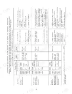
| Special Service Tools Required | 6 | Fes Tools, Otc Tools, Gauges Required, Fes 123 Hydrostatic Tractor Tool Kit |
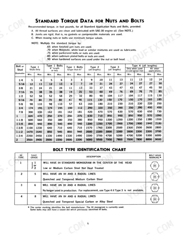
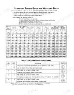
| Standard Torque Data for Nuts and Bolts | 7 | Recommended Torque Data Introduction, Standard Torque Data Table, Torque Multipliers Note, Bolt Type Identification Chart |
| Specifications | 8-10 | Pressures, Pump Capacities, Bearing Fits, Tolerances, Spring Specifications, Special Torques, Valves |
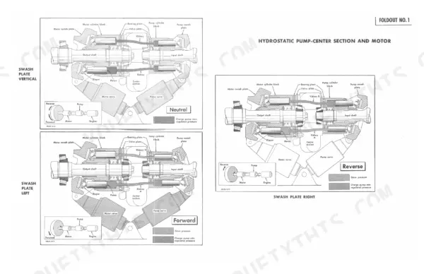
| Principles of Hydrostatics | 11-16 | General, How It Works (Variable Displacement Pump and Variable Displacement Motor), Servo Cylinders, Center Section |
| Operating Principles | 17-20 | Hand Controlled Models (Neutral, Forward, Reverse), Foot Controlled Models (Neutral |
| Familiarization and Component Identification | 21-24 | Hydrostatic Components Front View, Hydrostatic Components Right Rear View, Hydrostatic Components Left Rear View, Motor Side of Center Section, Pump Side of Center Section |
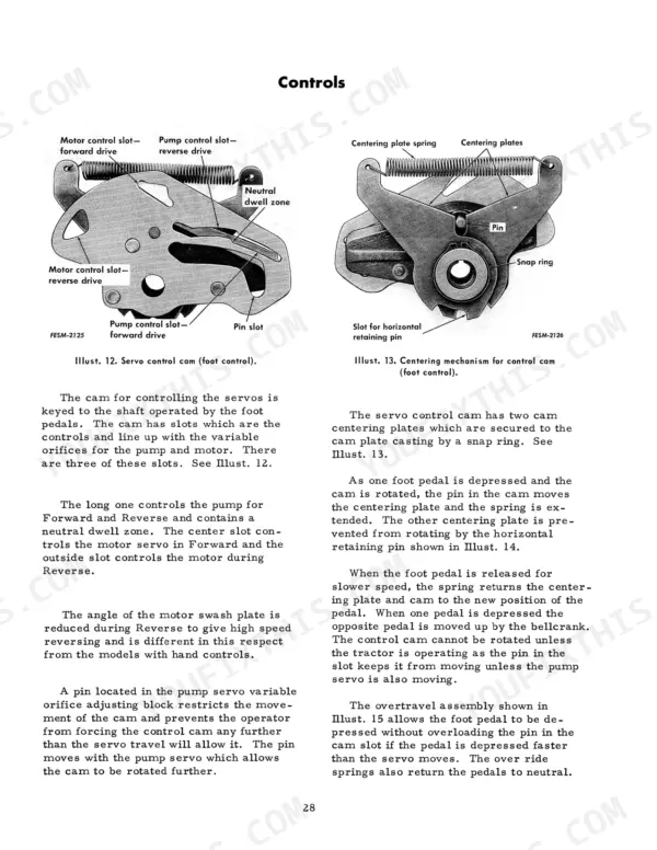
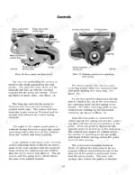
| Controlling the Tractor | 25-30 | Hand Controlled Models (High-Low Range Selector, Speed-Ratio Control, Foot-N-Inch Valve and Drive Control Valve, Foot-N-Inch Valve, Drive Control Valve) |
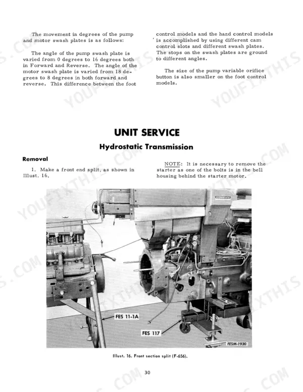
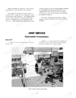
| Unit Service | 31-63 | Hydrostatic Transmission Removal (Front End Split, Fuel Tank and Steering Support Removal, Transmission Housing Removal) |
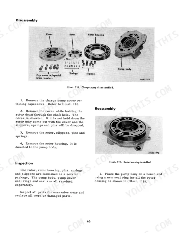
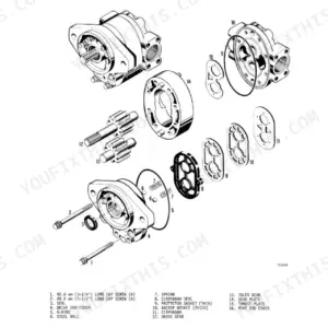
| Servicing Components | 64-74 | Servo Cylinders (Removal, Disassembly, Inspection, Reassembly), Charge and Servo Pump (Servo Relief Valve Improvements, Removal, Reassembly, Inspection) |
| Range Transmission and Mph Drive | 75 | Range Transmission Overview, Mph Drive Cable Disconnection, Mph Drive Cable Removal |
| Hydraulic and Differential Lubrication Circuits | 76 | Hydrostatic Tractor Differences, Hitch Pump Supply, Oil Cooler Connection, Differential Lube Flow, Manual Steering Make-Up Oil, Power Steering Relief Valve, System Oil Level Check |
| Adjustments | 77-83 | Hand Controlled Models (Neutral Adjustment for Servo Control and Linkage, Foot-N-Inch Valve Adjustment, Drive Control Valve Adjustment, S-R Lever Assembly Neutral Adjustment) |
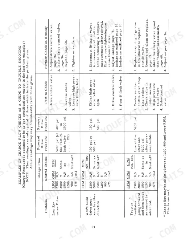
| Testing and Trouble Shooting | 84-101 | Checking Pressures and Charge Pump Flow (General, Method of Checking Drive Pressure, Charge Pump Pressure and Flow, Charge Pump Flow Used in Trouble Shooting), Servo Pump Pressure |
| Safety Starting Procedure | 102-116 | Operating Temperatures, Safety Starting Procedure Caution, Safety Starting Procedure Steps |
Quick Reference Specifications
| Specification | Value | Page |
|---|---|---|
| Pump cylinder block spring free length | 1-9/32 inches | p. 9 |
| Pump cylinder block spring total number of coils | 3-1/2 | p. 9 |
| Hydraulic filter replacement interval (second change) | 100 hours | p. 63 |
| Hydraulic filter replacement interval (each change thereafter) | 250 hours | p. 63 |
Case 544, 656, H70, H80 Common Problems This Manual Covers
Case 544 hydrostatic transmission suddenly stops moving forward or backward
Pull the drive control valve and check the ball and seat sealing surfaces for scoring before assuming pump failure. Verify charge pump flow first on the test port; charge pressure below 500 PSI points to a worn charge pump or a relief valve stuck open. Check drive pressure separately, it should hold above 5800 PSI under load, per the checks on page 98.
Manual Section: Tractor Propulsion Issues (No Forward/Reverse, Low Power) p. 98Hydraulics weak on remote valves, power steering choppy and loud with system whine
Check for aeration first, a whining pump almost always means the system is pulling air rather than wearing out. Inspect suction line fittings, the dipstick tube seal, and pump inlet O-rings for leaks that let air in without letting oil out. Confirm charge pressure at the test port; readings under 500 PSI confirm cavitation is starving the pump. Bleed the system per the air leak diagnosis on page 84.
Manual Section: Air Leaks Diagnosis p. 84Dark, thick hydraulic fluid with a transmission that keeps overheating
Drain the reservoir and inspect the fluid for metal fines, dark burnt oil usually means thrust plates or the ball guide are wearing and shedding material into the circuit. Replace both hydraulic filters immediately regardless of hours logged; the regular interval is 100 hours for the second change and 250 hours for every change after that, per page 63. Check oil cooler flow and clean any restriction before refilling, since restricted cooling drives the overheating on page 102.
Manual Section: Operating Temperatures Troubleshooting p. 102Slow to change directions and not reaching transport speed at full throttle
Check servo pump pressure before touching the drive control valve, a weak servo signal is the usual reason the swashplate won't stroke fast enough to hit transport speed. Verify the neutral adjustment on the servo control linkage isn't dragging the swashplate off center, per the adjustment steps on page 77. Confirm charge pump flow is adequate under load; a pump barely keeping up will show sluggish direction changes and no power at speed, covered on page 100.
Manual Section: Tractor Speed and Deceleration Problems p. 100Creep or drift in neutral when the speed control lever is centered
Adjust the neutral setting on the servo control and linkage before suspecting internal wear, most creep complaints trace back to a linkage that's drifted out of true center. Loosen the adjustment clevis, center the lever, and reset per the procedure on page 77. Recheck under load since creep that persists after adjustment points to a leaking servo cylinder seal rather than linkage misalignment.
Manual Section: Servo Control and Linkage Adjustment p. 77Engine block and head corrosion showing up after several seasons of use
Drain and flush the cooling system anytime antifreeze looks rusty or has gone past its service life, corrosion damage on these engines almost always traces back to neglected coolant rather than a manufacturing defect. Refill with the correct antifreeze/water mix and pressure test the system for external leaks before returning the tractor to work. Inspect the block and head for pitting at every coolant service going forward, since caught early it's a flush, caught late it's a casting replacement.
Frequently Asked Questions
Torque specs for the servo relief valve on hydrostatic tractors?
The servo pressure relief valve, rated at 400 psi, should be torqued to 18 ft. lbs. when installed into the charge pump. This specific torque ensures proper function and prevents distortion of the valve body. p. 9
What are the replacement specifications for Hydraulic pump (Charge pump)?
The Hydro-Pump has a capacity of 4.26 cubic inches per revolution at 18 degrees, and the Hydro-Motor has a capacity of 7.24 cubic inches per revolution at 18 degrees. The approximate charge pump flow in "Neutral" with oil at 135 degrees F is 10.5 gallons per minute (gpm) at an engine RPM of 2300. p. 8
What are the replacement specifications for Hydraulic filters?
The filter assembly part number is 391 557 R91, which uses element 381 256 R91. After the initial hydraulic system clean-up procedure, the filter should be changed after two hours of operation, then again after the first ten hours, and subsequently every 100 hours for the second change and 250 hours for each change thereafter. p. 90
What is the specified torque for the flex plate retaining capscrews?
The flex plate retaining capscrews should be tightened to a torque of 20 ft. lbs. This ensures the flex plate is securely centered in the flywheel bore without stressing or deforming its legs. p. 9
What format is this Hydrostatic Drive Tractors manual in?
A 116-page Service Manual in searchable PDF format, available the moment you complete checkout. View on computer, tablet, or phone, with no shipping wait.
Is this Hydrostatic Drive Tractors Service Manual printable?
Absolutely. No DRM or copy protection. Print the whole manual or just the pages you need. Any home or office printer works.
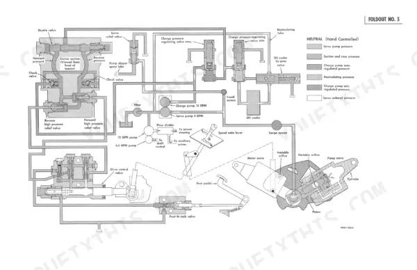
Can I find hydraulic circuit diagrams in this Hydrostatic Drive Tractors manual?
Yes, this Hydrostatic Drive Tractors Service Manual includes hydraulic system diagrams, circuit schematics, and component specifications.