Part of the Case Repair Manuals.
Case issued this book as Rac 8-97121, the factory service manual for the 8840 self propelled windrower, and this Case 8840 service manual PDF reproduces all 850 pages of it. Hydrostatic ground drive gets the deepest coverage: schematics trace oil from the charge pump through the tandem pump to the drive motors, backed by pressure tests and troubleshooting for the two speed control valve. Full electrical schematics support the instrument and troubleshooting sections, while the header lift and flotation valve, guard angle valve, and bypass valve each carry their own teardown and adjustment procedures. Before you condemn the hydrostatic pump, check inductive sensor resistance against the 3.1 to 3.2 k ohm spec, and pull wheel nuts to 200 lb-ft (271 N-m). A down windrower in cutting season stalls on one missing pressure number. This bookmarked, text searchable file rides on your laptop or phone to whichever field the machine quit in.
What's Inside This Manual
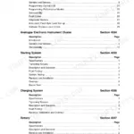
| System | Pages | Key Topics |
|---|---|---|
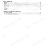
| General | 3-38 | Introduction, Safety Rules, General Machine Specifications, And Standard Torque Specifications, Maintenance and Lubrication, Decals, Specification Details |
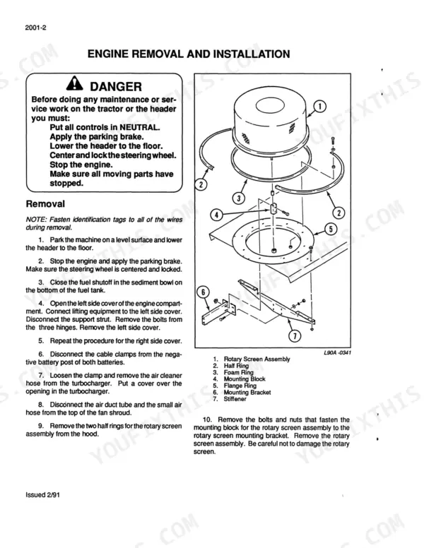
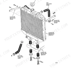
| Engine | 39-260 | Engine Removal and Installation and Radiator Removal and Installation, Engine Accessories, Cylinder Head and Valve Train, Cylinder Block, Lubrication System, Cooling System |
| Fuel System | 261-316 | Fuel System and Engine Controls, Fuel System and Filters, Fuel Injectors, Bosch Fuel Injection |
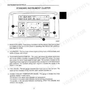
| Electrical System | 317-358 | Removal and Installation of Electrical Components, Specifications, Instruments, Schematics, Troubleshooting |
| Steering | 359-386 | Removal and Installation of Steering Components, Steering Control Linkage Troubleshooting and Adjustments |
| Power Train | 387-526 | Ground Drive Hydraulic System Specifications, Charge Pump, Tandem Pump, Drive Motors, Two Speed Control Valve and Two Speed Cylinder, Drive Controls, Drive Shafts, Chain Cases |
| Brakes | 527-534 | Parking Brake |
| Hydraulic System | 535-664 | Hydraulic System Specifications, Cleaning the Hydraulic System, Header Drive Pump, Header Drive Motor, Header Lift and Flotation Valve, Guard Angle Control Valve, And Bypass Valve |
| Chassis | 665-850 | Removal and Installation of Air Conditioning Components, Air Conditioning Troubleshooting and System Checks, Air Conditioning System, Cab, Header |
Every system also includes an index.
Quick Reference Specifications
| Specification | Value | Page |
|---|---|---|
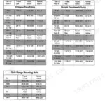
| Wheel nuts torque | 200 LB-FT (271 N-m) | p. 14 |
| Wheel bolt torque | 110 to 130 LB-FT (149 to 176 N-m) | p. 14 |
| Battery, minimum cranking capacity at 0°F | Two 12 V, 450 amp | p. 14 |
| Voltmeter reading variance | 1/2 volt | p. 354 |
| Inductive sensor resistance | 3.1 to 3.2 k ohms | p. 356 |
| Charge Pump Total Output | 14.5 gpm (54.9 L/min) | p. 416 |
| Spool movement clearance | 3/16 IN (4.8 mm) | p. 611 |
| Main System Relief Pressure | 5000 psi | p. 14 |
| Header Lift Relief Pressure | 2000 psi | p. 15 |
| Engine High Idle | 2500 rpm | p. 14 |
| Wheel Nut Torque (Drive Wheels) | 200 LB-FT | p. 14 |
| Wheel Nut Torque (Rear Caster Wheels) | 110 to 130 LB-FT | p. 14 |