
Part of the Case Repair Manuals.
Looking for the Case CX17B service manual PDF your dealer works from? All 678 pages of this factory manual (OEM #87492465) cover the CX17B mini excavator, from crawler frame and travel motors up to the canopy. Inside: full hydraulic circuit schematics for the travel, slew, and bucket circuits, complete electrical diagrams with harness connection charts, and page after page of disassembly procedures for the hydraulic pump, control valve, slewing motor, and swivel joint. You also get a real troubleshooting section that walks hydraulic and engine faults back to the failed component, plus full engine service data for the fuel, cooling, and lubrication systems. Set the 1/4 PF piping joints to 36 N-m and the 1/2 PF fittings to 108 N-m; confirm the starter tests at 12V and 1.7 kW. Your machine is down and every hour costs money. Bookmarked with a real text layer: search any spec, jump straight to the section, and get back to digging.
Other edition of this manual
What's Inside This Case CX17B Manual
| System | Pages | Key Topics |
|---|---|---|
| Cx17B | 1-12 | Service Manual, Safety Precautions, General Safety Information |
| Outline | 13-22 | General Precautions, Preparation Before Disassembling, Safety in Disassembling and Assembling, Hydraulic Equipment, Electrical Equipment, Welding Repair |
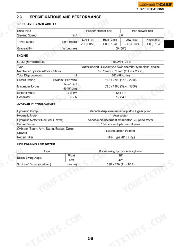
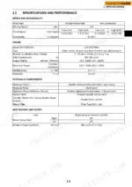
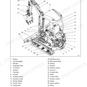
| Specifications | 23-38 | Components Name, Machine Dimensions, Specifications and Performance, Machine and Components Weight, Engine Specifications |
| Attachment Dimensions | 39-58 | Boom, Arm, Bucket, Dozer, Swing |
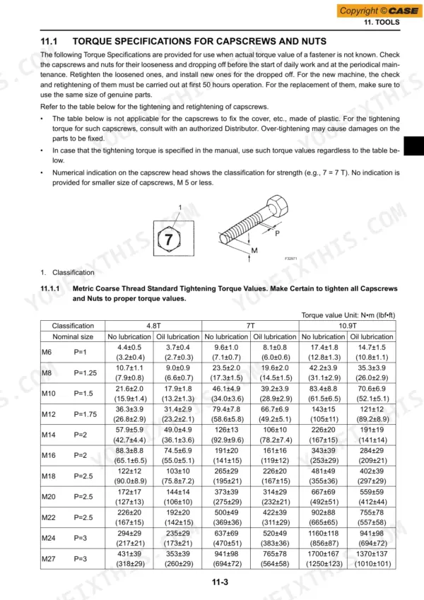
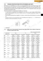
| Tools | 59-72 | Torque Specifications, Capscrews and Nuts, Joints and Hoses, Sleeve Type Tube Fittings, Special Tools |
| Standard Maintenance Timetable | 73-84 | Standard Maintenance Time Table, Maintenance of Excavator |
| Maintenance Standards Andtest Procedures | 85-104 | Performance Inspection, Engine Speed, Hydraulic Oil Pressure, Travel Performances, Slew Performances, Attachment Operating Performances |
| Hydraulic System | 105-118 | Hydraulic Circuits, Component Models, Hydraulic Circuit Operation, Travel Operating Circuit, Slew Operating Circuit, Bucket Operating Circuit |
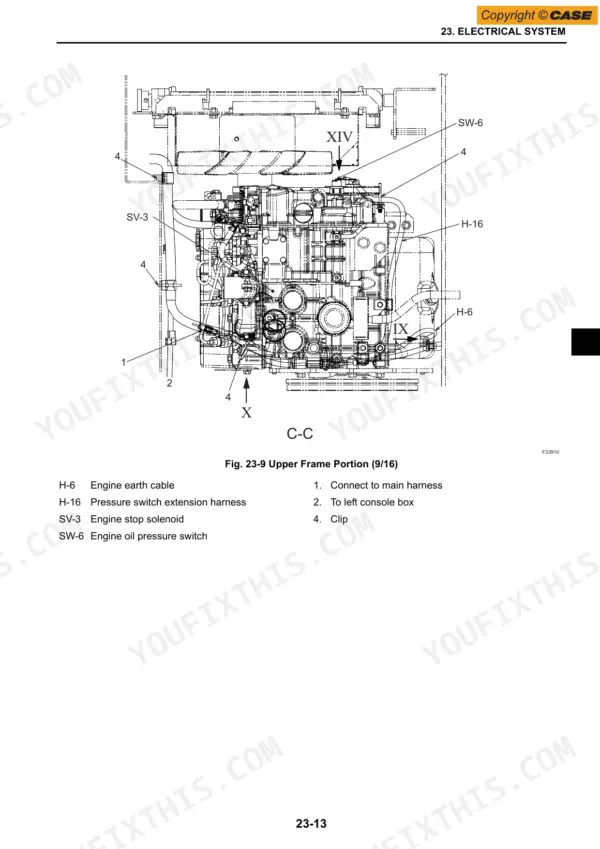
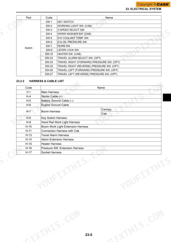
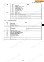
| Electrical System | 119-158 | Circuit Diagram, Harness Connection, Electrical Equipment List, Harness List, Component Arrangement |
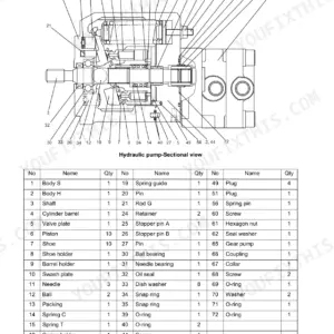
| Components System | 159-236 | Hydraulic Pump, Pilot Valve, Control Valve, Slewing Motor, Travel Motor, Swivel Joint |
| General Disassembly and Assembly | 237-242 | General Disassembly, General Assembly, Tightening Torque Specifications |
| Attachments | 243-276 | Bucket, Arm, Boom, Swing, Dozer, Cylinder |
| Upper Slewing Structure | 277-404 | Canopy, Counterweight, Hydraulic Oil Tank, Fuel Tank, Pump, Control Valve |
| Travel System | 405-464 | Crawler, Slide Plate, Lower Roller, Front Idler, Sprocket, Travel Motor |
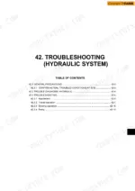
| Troubleshooting (Hydraulic System) | 465-490 | Attachment Operation, Travel Operation, Slewing Operation, Pump Troubleshooting |
| Troubleshooting (Engine) | 491-504 | Starting Trouble, Engine Rotation Trouble, Output Drops Down, Other Engine Trouble |
| Engine | 505-658 | Main Components, Fuel System, Lubrication System, Cooling System, Inlet/Exhaust Systems, Engine Components |
| Supporting Data | 659-678 | Hydraulic Circuit Diagram, Standard Specification, Hydraulic Circuit Operation, Schematic Piping, Electric Circuit Diagram |
Quick Reference Specifications
| Specification | Value | Page |
|---|---|---|
| Starter capacity | 12 V x 1.7 kW | p. 34 |
| Tightening torque for joints for piping (1/8 PF) | 17±2 N·m (12±1 lbf·ft) | p. 65 |
| Tightening torque for joints for piping (1/4 PF) | 36±2 N·m (27±1 lbf·ft) | p. 65 |
| Fuel filter replacement time | 0.1 hour | p. 76 |
| Air cleaner element replacement time | 0.1 hour | p. 76 |
| Tightening torque for nut (2) (Slewing Motor: Relief Valve) | 34.3 N·m (25.3 lbf·ft) | p. 95 |
| Tightening torque of battery terminal | 3.4 N•m (2.5 lbf•ft) | p. 126 |
| Engine Output Rating | 11.3 kW | p. 29 |
| Maximum Torque | 53.5 N•m | p. 29 |
| Fuel Injection Pressure | 13.7 MPa | p. 34 |
| Slewing Speed | 8.6 min-1 | p. 29 |
| Main Relief Valve Pressure (P1, P2) | 21.6 MPa | p. 89 |
Case CX17B Common Problems This Manual Covers
Case CX17B won't move at all, engine runs fine but both tracks stay dead
Check hydraulic oil level and inspect the return filter for clogging before condemning the main pump. Test the servo circuit next; pilot relief pressure should hold 3.5 MPa (page 95). If pilot pressure reads near zero, work through the travel circuit procedures starting on page 465. A stuck safety valve or low servo pressure kills both tracks.
Manual Section: Troubleshooting (Hydraulic System) p. 465One track drags or refuses to move, machine steers itself to one side
Swap the travel lines side to side at the swivel joint to isolate the motor from the control valve. Test main relief pressure on the affected circuit; both P1 and P2 should read 21.6 MPa (page 89). If one side tests low, follow the travel troubleshooting chart on page 465 before pulling the travel motor.
Manual Section: Troubleshooting (Hydraulic System) p. 465Engine cranks but won't start, or fires then stalls repeatedly in cold weather
Check for air in the fuel system and replace the fuel filter; the schedule books it at 0.1 hour (page 76). Bleed the lines back to the injection pump, then verify battery cables and torque the terminals to 3.4 N·m (page 126). If it still won't fire, run the starting checks beginning on page 491.
Manual Section: Troubleshooting (Engine) p. 491Bucket curls slowly and digging force falls off once the hydraulic oil warms up
Drain a sample from the tank and check the oil; dark or milky fluid means heat damage or water. Test main relief pressure against the 21.6 MPa spec on page 89, then verify pilot pressure at 3.5 MPa (page 95). Adjust the relief valve as needed and torque its lock nut to 19.6 N·m.
Manual Section: Maintenance Standards Andtest Procedures p. 89Hydraulic system runs hot and whines loudly after an hour of steady digging
Check tank oil level first; a low tank lets the pump cavitate, which makes the whine and the heat. Inspect suction side fittings for air leaks and retorque any loose hose ends; 1/4 PF hydraulic hoses take 29±4.9 N·m (page 65). Replace the hydraulic filter if it has never been changed.
Manual Section: Hydraulic Pump TroubleshootingFrequently Asked Questions
What is the tightening torque for the cylinder head bolts on the CX17B engine?
The main cylinder head bolts for the engine must be tightened to a torque of 73.5 to 83.4 Nm (54.2 to 61.5 lbf-ft). The sub bolts for the cylinder head should be tightened to 19.6 to 29.4 Nm (14.4 to 21.6 lbf-ft). p. 118
What is the standard valve clearance for the engine?
The standard valve clearance for both the inlet and drain valves on the engine is 0.25 mm (0.0098 in) when the engine is cold. p. 112
What is the procedure for bleeding air from the hydraulic cylinder?
After removing or installing a cylinder, start the engine and let it idle for 5 minutes. Extend and retract the cylinder 4 or 5 times at a slow speed, keeping the rod 100 mm (4 in) short of the stroke end. Finally, perform the procedure at high idling speed, then move the piston rod to its stroke end at low idling speed to reach the relief condition. p. 135
What is the standard compression pressure for the engine?
The standard compression pressure for the engine at 280 RPM is 2.7 MPa (28 kgf/cm²) [398 psi]. If the pressure is at or below 2.2 MPa (22 kgf/cm²) [313 psi], it is not acceptable. p. 122
What is the tightening torque for the main bearing cap bolts?
The main bearing cap bolts on the engine should be tightened to a torque of 49.0 to 53.9 Nm (36.1 to 39.7 lbf-ft). p. 118
Is this Case CX17B Service Manual a digital download?
A single searchable PDF file of 678 pages, downloadable right after payment. Nothing ships, nothing waits in the mail.
Can I print pages of this Case CX17B manual for my own shop?
Yes. Many buyers print one chapter at a time for their own shop and keep the rest on a tablet.









Reviews
There are no reviews yet.