


![Case IH 274 284 Shop Repair Manual [Tractor]](https://youfixthis.com/wp-content/uploads/2013/10/YouFixThis-Kawasaki-Screen-11-300x300.png)
Service Repair Manual For Case CX350C Tier 4. Include detailed step by step Instructions, diagrams, illustrations for disassembly and assembly. Make an easy any repair, overhaul, testing, adjustment, teardown, replacement and change, inspection.
= Clickable index
= Bookmarks
= Searchable Text
= Printable
= Zoomable
MODELS Covered
Case CX350C Tier 4
SECTIONS covered
GENERAL INFORMATION
Safety, general information and standard torque data
Specifications
Main Equipment Table
Main Unit Weight
Maintenance Standards
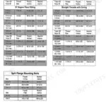
Bolt Size and Torque Table
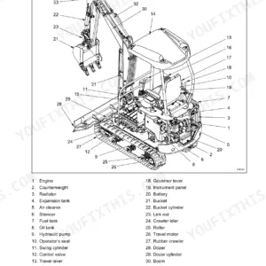
Overall View
List of special took
Fluids And Lubricants
Conversion Table
Abbreviations
ENGINE
Removal and Installation of Engine Assembly
Removal and installation of the fuel cooler
Removal and Installation of Turbo Charger
Removal and Installation of EGR Cooler and EGR Valve
Removal and Installation of Engine Hood
Removal and Installation of Muffler
Primary specifications
Removal and Installation of Cylinder Head
Removal and Installation of Cylinder Block
Lubrication System
Cooling System
Removal and Installation of Exhaust Manifold
Disassembly, Removal and Installation of DPD Assembly
FUEL SYSTEM
Removal and Installation of Fuel Tank
Removal and Installation of Fuel Supply Pump NA
Removal and Installation of Common Rail Assembly NA
Removal and Installation of Injector
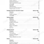
ELECTRICAL SYSTEM
Electrical and Engine Basic Functions
Service Support
Function. Structure. Operation
Symptom
Functional Inspection
Maintenance precautions
Removal and Installation of Starter Motor
Removal and Installation of Alternator
Preheating System
Electrical Equipment Layout Diagram
Connection Connector Pin Layout
Sequence Circuit Diagram
Engine side DTC List S4402832
Main Unit side DTC List
Introduction to the trouble diagnosis
Engine Control System
Engine side Trouble
Main Unit side Trouble
Data Reference Values
Electrical Wiring Diagram
UNDERCARRIAGE
Removal and Installation of Shoe Assembly
Removal and Installation of Shoe Plate
Removal and Installation of Upper Roller
Assembly and Disassembly of Upper Roller
Removal and Installation of Lower Roller
Assembly and Disassembly of Lower Roller
Removal and Installation of Sprocket
Removal and Installation of Takeup Roller NA
Assembly and Disassembly of Takeup Roller NA
Removal and Installation of Grease Cylinder
Assembly and Disassembly of Grease Cylinder
DRIVE TRAIN
Removal and Installation of Travel Motor |
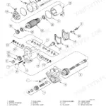
Assembly and Disassembly of Travel Motor
Removal and Installation of Suing Unit
Assembly and Disassembly of Swing Unit
UPPERSTRUCTURE HYDRAULICS
Overall Mew
Port Diagram
Pressure Measurement and Adjustment Procedures
Hydraulic Pump Flow Measurement Procedures
Volume Measurement Procedures
Air Bleed Procedure
Removal and Installation of Hydraulic Oil Tank NA
Removal and Installation of Hydraulic Pimp
Removal and Installation of Control Valve
Removal and Installation of Bucket Cylinder
Removal and Installation of Arm Cylinder
Removal and Installation of Boom Cylinder
Removal and Installation of Center Joint
Removal and Installation of Travel Remote Control Valve
Removal and Installation of Operation Remote Control Valve
Removal and Installation of 4 Stack Solenoid NA
Removal and Installation of 4 Stack Solenoid NA
Removal and Installation of Cushion Valve
Procedures for Assembly and Disassembly of Hydraulic Pump Mam
Pump Mam Unit Maintenance Standards
Procedures for Assembly and Disassembly of Control Valve
Procedures for Operation Assembly and Disassembly of Hydraulic Cylinder
Procedure: for Assembly and Disassembly of Operation Remote Control
Procedures for Assembly and Disassembly of Travel Remote Control
Assembly and Disassembly of Cushion Valve
Removal and Installation of Aim HBCV
Removal and Installation of Boom HBCV
Assembly and Disassembly of Center Joint
Assembly and Disassembly of Swing Motor
Explanation of Hydraulic Circuit and Operations (standard model)
Explanation of Hydraulic Circuit and Operations (option)
Structure and Operation Explanation of Hydraulic Pump
Structure and Operation Explanation of Travel Motor
Structure and Operation Explanation of Swing Motor
Structure and Operation Explanation of Control Valve
4 Stack Solenoid Valve Operation Explanation
Structure and Operation Explanation of Upper Pilot Valve
Structure and Operation Explanation of Travel Pilot Valve
Structure and Operation Explanation of Cushion Valve
UPPERSTRUCTURE
Removal and Installation of Counterweight
Removal and Installation of Bucket
Removal and Installation of Bucket Link
Removal and Installation of Arm
Removal and Installation of Boom
Removal and Installation of Operator’s Se3t
Removal and Installation of Cab Assembly
Removal and Installation of Wiper
Removal and Installation of Wiper Controller
Removal and Installation of Wiper Motor
Removal and Installation of Monitor
Removal and Installation of Cab Front Glass NA
Window Lock Adjustment Procedures
Tightening torque
Air Conditioner Overall Diagram
Assembly and Disassembly of An Conditioner Units NA
Removal and Installation of Compressor
Removal and Installation of Condenser
Removal and Installation of Receiver Dryer
Work Precautions
ELECTRICAL SCHEMATICS
HYDRAUUC SCHEMATIC
Searches:
Part number 84402832


Reviews
There are no reviews yet.