

Part of the Case Repair Manuals.
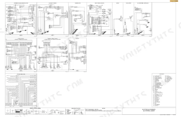
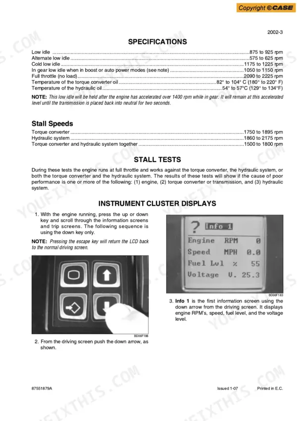
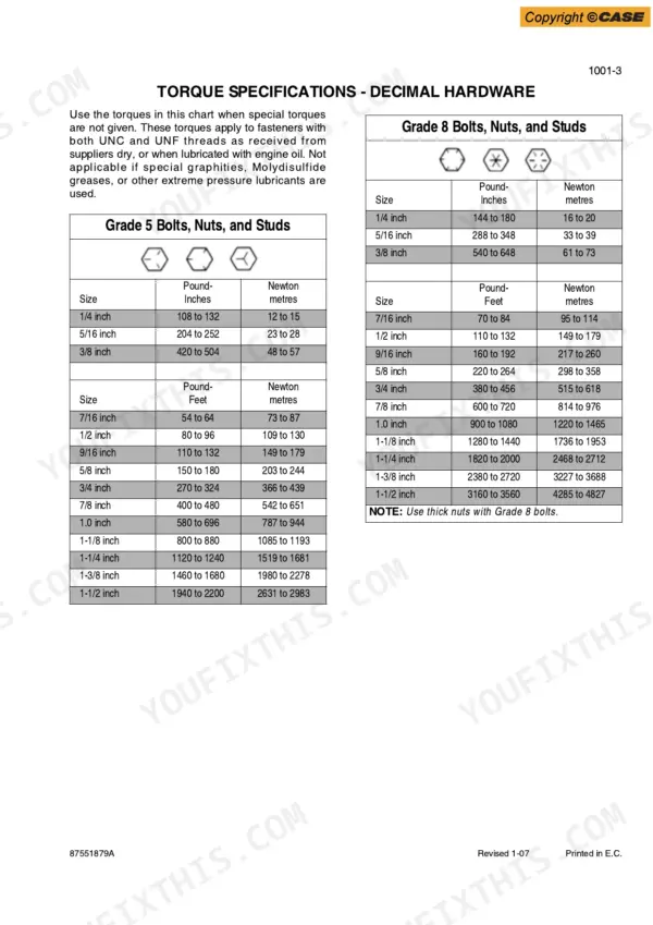
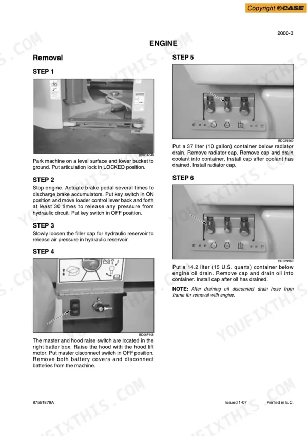
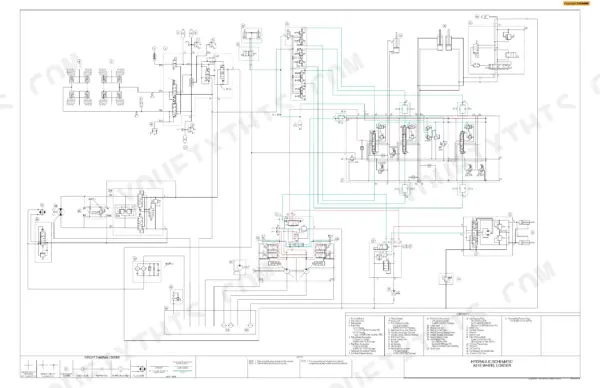
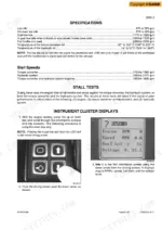
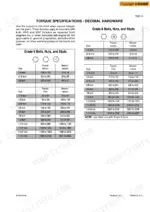
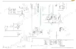
This 806-page Case 821E Service Manual PDF (OEM #87551879A) puts the whole Wheel Loader on your bench: engine, fuel system, electrical, steering, power train, brakes, hydraulics, and mounted equipment. Inside: fold-out electrical and hydraulic schematics, a full troubleshooting section for transmission and brake pressure checks, and page after page of removal and installation procedures. You also get error code listings, stall test steps, and factory torque tables for every fitting size on the machine. Torque the 3/4-inch O-ring face seal fittings to 90 to 110 N-m, then drain the engine oil into a 14.2-liter container before you pull the pan. Your loader is down and every hour costs money. Get the factory numbers, not forum guesses. This bookmarked PDF opens on any device; search any spec by keyword and get back to wrenching.
What's Inside This Case 821E Manual
| System | Pages | Key Topics |
|---|---|---|
| General | 4-27 | Section Index - General (Standard Torque Specifications, Fluids and Lubricants, Metric Conversion Chart) |
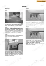
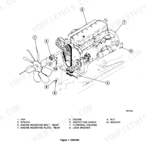
| Engines | 28-67 | Section Index - Engines (Engine and Radiator Removal and Installation, Stall Tests, After Cooler) |
| Fuel System | 68 | Section Index - Fuel System |
| Electrical | 69-303 | Section Index - Electrical (Removal and Installation of Starter and Alternator, Electrical Specifications and Troubleshooting, Batteries, Instrument Cluster) |
| Steering | 304-357 | Removal and Installation of Steering Components, Steering Specifications, Pressure Checks, And Troubleshooting, Steering Cylinders, Center Pivot, Auxiliary Steering Motor and Pump |
| Power Train | 358-543 | Removal and Installation of Power Train Components, Transmission Specifications, Pressure Checks, And Troubleshooting, Transmission, Front Axle, Drive Shafts, Center Bearing |
| Brakes | 544-583 | Section Index - Brakes (Removal and Installation of Brake Components, Hydraulic Brake Troubleshooting, Brake Pump, Brake Accumulators, Parking Brake) |
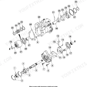
| Hydraulics | 584-711 | Removal and Installation of Hydraulic Components, Hydraulic Specifications, Troubleshooting, And Pressure Checks, Cleaning the Hydraulic System, Hydraulic Pump |
| Mounted Equipment | 712-803 | Section Index - Mounted Equipment (Air Conditioning Troubleshooting and System Checks for Systems with HFC-134a Refrigerant, Air Conditioner System Service, Removal and Installation of Air Conditioning and Heater Components, Loader, Rollover Protective Structure Cab Structural Frame, Cab Glass Installation) |
| Electrical Schematic Foldouts and Hydraulic Schematic Foldout | 804-806 | Starting and Charging System, Power Relay Modules, Engine Controller, Transmission Shifter, Warning Buzzer, Instrument Cluster, Switch Pad, Back Up Alarm Controls |
Quick Reference Specifications
| Specification | Value | Page |
|---|---|---|
| O-ring Face Seal End - 1/4 inch (6.4 mm) - 9/16-18 | 120 to 144 Pound Inches (14 to 16 Newton metres) | p. 15 |
| O-ring Face Seal End - 3/8 inch (9.5 mm) - 11/16-16 | 216 to 240 Pound Inches (24 to 27 Newton metres) | p. 15 |
| Radiator drain container capacity | 37 liter (10 gallon) | p. 32 |
| Engine oil drain container capacity | 14.2 liter (15 U.S. quarts) | p. 32 |
| bottom radiator hose clamp torque | 10.1 to 11.3 Nm | p. 49 |
| Pressure setting for steering priority valve | 239 to 243 bar (3465 to 3525 psi) | p. 329 |
| Rear drive shaft bolts torque | 61 to 81 Nm (45 to 60 pound feet) | p. 380 |
| Before the Converter - Opening Pressure | 8 bar (116 psi) | p. 394 |
| Behind the Converter - Opening Pressure | 2.5 bar (36 psi) | p. 394 |
| Steering limit pressure | 239 to 243 bar (3465 to 3525 psi) | p. 630 |
| End plate mounting bolts | 70 Nm (51.5 pound feet) | p. 668 |
| Engine Oil Capacity with Filter Change | 21 liters | p. 18 |
Case 821E Common Problems This Manual Covers
Case 821E transmission calibration won't complete, monitor shows CALIB G/B and calibration condition error
Verify transmission oil is at operating temperature, the transmission is in neutral, and the park brake is applied before starting calibration. Run the clutch pressure checks for K1 through K4 with the transmission pressure-check procedure on page 394 and compare each reading against the chart printed there. Decode the CALIB G/B prompt using the error code reference on page 16 before chasing hardware.
Manual Section: Transmission Specifications, Pressure Checks, and Troubleshooting p. 394Hydraulics feel weak, bucket lift and tilt slow, implement response unstable under load
Check reservoir oil level first; refill capacity is 90 liters, listed with the fluid specs on page 18. Replace restricted filters if the restriction light flashes. Then run the hydraulic pressure checks, comparing loader and steering limit readings; steering limit should hold 239 to 243 bar (3465 to 3525 psi) per page 630.
Manual Section: Hydraulic Specifications, Troubleshooting, and Pressure Checks p. 630Steering heavy or slow to respond, gets worse at low engine RPM
Test steering priority valve pressure with the engine at full throttle and the wheels held against a steering stop. Compare the reading to 239 to 243 bar (3465 to 3525 psi), the setting given on page 329. Low pressure points to a worn priority valve or internal leakage; inspect hoses and O-rings disturbed during recent service before condemning the valve.
Manual Section: Steering p. 329Engine overheating on long pushes, coolant temperature gauge climbing toward the red zone
Check coolant level with the engine cold; full system capacity is 40.9 liters per page 18. Clean the radiator, fuel cooler, and condenser stack with low pressure air, blowing opposite the normal airflow direction. Pressure test the cap, inspect hose connections for seepage, and torque radiator hose clamps to 10.1 to 11.3 Nm as specified on page 49.
Manual Section: Engines p. 49Hydraulic hard line seeping from pinhole crack, fittings still weeping oil after retorque
Clean the area, run the machine, and trace the leak to its exact source before pulling anything apart. Replace cracked hard lines; do not braze or weld them. When reconnecting O-ring face seal fittings, install new O-rings and torque to the chart on page 15; a 9/16-18 fitting takes 120 to 144 pound inches (14 to 16 Nm).
Manual Section: Hydraulics p. 584Frequently Asked Questions
How do you calibrate the clutch pack on a Case 821E wheel loader?
To calibrate the transmission clutches, ensure the machine is running with warm transmission oil, the engine low idle speed is correct, the transmission is in neutral, and the park brake is applied. Press and hold the enter key for 2 to 3 seconds to access the SELECT menu, use the down arrow to highlight CONFIG, then CALIB G/B. Follow the on-screen prompts to adjust clutches K1, K2, K3, K4, KV, and KR. p. 392
How do you retrieve fault codes on a Case 821E?
To access fault codes, press and hold the escape key and the up arrow key simultaneously for more than 2 seconds. The instrument cluster will then display the stored fault codes. p. 285
What is the torque specification for the bucket teeth bolts on a Case 821E?
The bolts for the bucket teeth must be tightened to a torque of 1315 to 1480 Nm (970 to 1090 pound-feet). p. 774
What is the engine oil capacity for the Case 821E?
The engine oil capacity for the Case 821E, including the filter change, is 21 liters (22 U.S. quarts). p. 18
What is the correct torque for the transmission pump screws on a Case 821E?
The transmission pump screws should be tightened to a torque of 46 Nm (407 pound inches). p. 404
What do I get after purchasing this Case 821E manual?
A 806-page Service Manual in searchable PDF format, available the moment you complete checkout. View on computer, tablet, or phone, with no shipping wait.
Can I print this Case 821E manual?
Yes. Print a chapter or just the pages for the job at hand, for use in your own shop. Any home or office printer works.









Reviews
There are no reviews yet.