
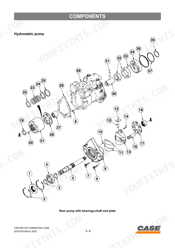
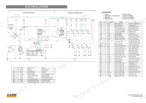
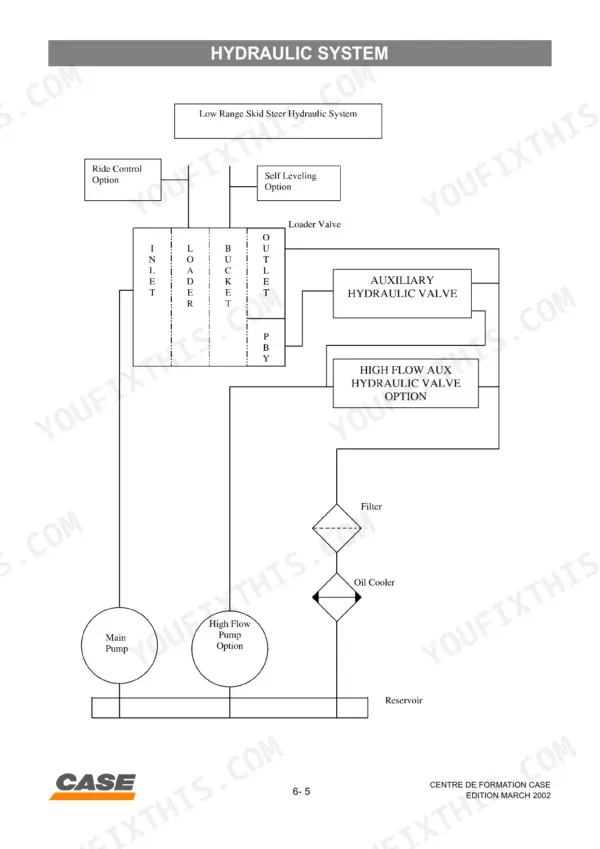
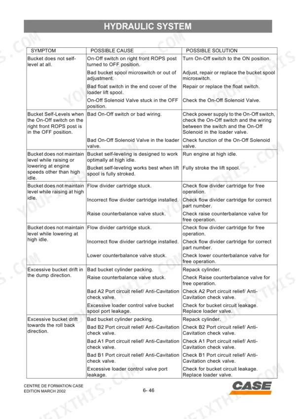
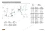

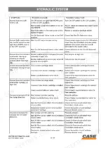
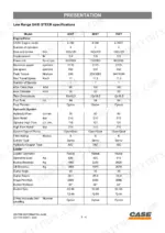
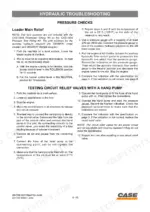
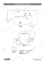
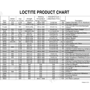
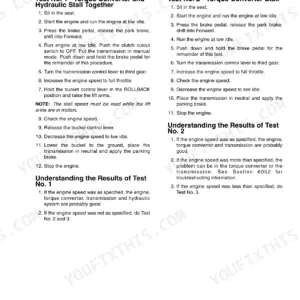
Part of the Case Schematics.
Getting your skid steer back on the dirt requires the right numbers, and this 214-page Case 40 XT, 60 XT, 70 XT service manual PDF breaks down the entire hydrostatic pump, auxiliary valves, and loader cylinders. Open to detailed wiring diagrams that trace every circuit from the fuse box directly to the spool lock solenoids. You also get full hydraulic schematics mapping the high flow circuit, alongside step-by-step troubleshooting trees for the self-leveling system. Coat the hydraulic pump input spline with 82.8 ml of Molykote Type Gn paste before assembly, and verify the leakage threshold stays within the 3.8 L/min tolerance during load testing. Chasing phantom pressure drops will drain your shop's profits. Download this bookmarked file, pull it up on your tablet, and fix the machine right the first time.
Other editions of this manual
What's Inside This Case 40 XT, 60 XT, 70 XT Manual
| System | Pages | Key Topics |
|---|---|---|
| Skid Steer Range | 2-3 | General Caracteristics, Low Range Specifications, Capacities and Lubrication, Engine Lubrication, Diesel Fuel System, Drive Selection |
| Presentation | 5-16 | General Characteristics, Low Range Specifications, Capacities and Lubrication, Engine Lubrication, Diesel Fuel System, Control Panels |
| Location of the Main Components | 17-28 | Hydraulic Pump, Hydrostatic Drive Pump, Hydraulic Drive Motor, Hydraulic Brakes, Loader Valve, Fuse and Relay Box |
| Components | 29-56 | Remote Controls, Hydrostatic Pump and Motor, Loader and Auxiliary Valves, Lift and Bucket Cylinders, High Flow Circuit, Filter Restriction Indicator |
| Electrical Circuit and Troubleshooting | 57-114 | Circuit Diagrams, Instrument Panels, Wiring Harness Testing, Troubleshooting Procedures, Electrical Components, Switches and Solenoids |
| Hydraulic System | 115-160 | Hydraulic System Overview, Loader Control Valve, Spool Lock Solenoids, Auxiliary Circuit, High Flow Hydraulics, Self-Leveling System Troubleshooting |
| Hydrostatic System | 161-212 | System Overview, Hydrostatic Pump and Motor, Parking Brake Systems, Control Linkage, System Cleanup, Troubleshooting and Adjustments |
Quick Reference Specifications
| Specification | Value | Page |
|---|---|---|
| All Models | ||
| Hydraulic pump input spline lubricating paste | 82.8 ml (2.8 ounce) tube of Molykote Type Gn paste is 384646R1 | p. 37 |
| Leakage threshold for hydraulic circuit | more than 3.8 L/min (one gpm) less than the flow indication at the same pressure in Test No. 1 | p. 167 |
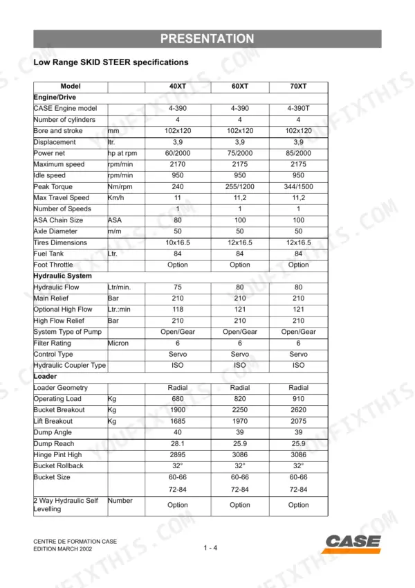
| Engine Displacement | 3.9 ltr. | p. 10 |
| Fuel Tank Capacity | 84 Ltr. | p. 10 |
| Electrical System Voltage | 12 Volts | p. 14 |
| Hydraulic Pump Maximal Service Pressure | 210 bar | p. 19 |
| Hydrostatic Drive Pump Maximal Pressure | 345 kPa | p. 20 |
| Loader Control Valve Main Relief Pressure | 20,700 kPa | p. 162 |
| Loader Raising Time | 4.1 seconds | p. 162 |
| 60XT, 70XT | ||
| Tires Dimensions | 12x16.5 | p. 10 |
| 40XT | ||
| Operating Load | 680 Kg | p. 10 |
| Power Net | 60/2000 hp at rpm | p. 10 |
Case 40 XT, 60 XT, 70 XT Common Problems This Manual Covers
Case 40 XT engine fails to start or runs erratically with sputtering after sitting in storage
Drain the fuel tank and check the water separator bowl for standing water before cranking again. The fuel tank holds 84 Ltr., so top off with fresh diesel after draining contaminated fuel completely. Replace the water separator element and bleed air from the fuel lines at the injector pump. Check wiring at the fuel solenoid pull in relay per the electrical fuel system troubleshooting if the engine still won't fire.
Manual Section: Electrical Fuel System Components TroubleshootingHydraulic system pressure drops below 124 bar during operation, bucket response feels weak
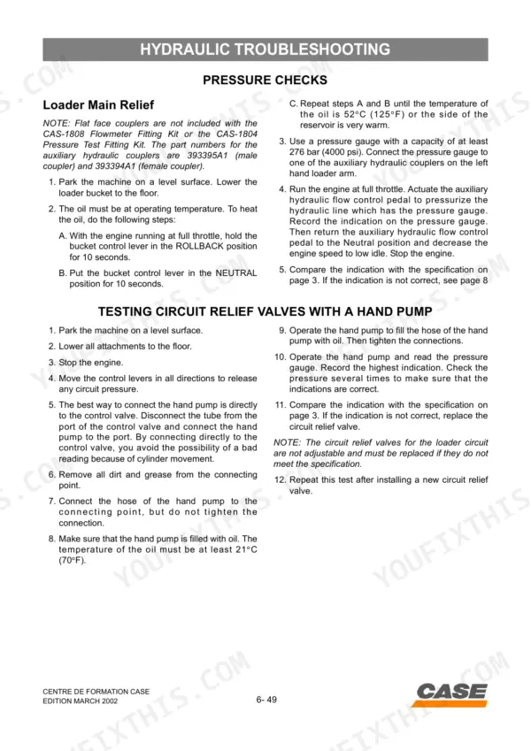
Hook up a flowmeter and run the pressure and flow tests for the loader circuits described. Check main relief pressure against the 20,700 kPa spec listed on page 162; if it reads more than 3.8 L/min (one gpm) below the baseline flow at the same pressure noted on page 167, the pump or seals are leaking internally and need teardown.
Manual Section: Hydraulic Pressure & Flow Tests (Loader Circuits)Unable to maintain throttle at 2000 rpm under load, engine bogs down on heavy lift
Check the air filter restriction indicator first; a clogged element chokes intake before governor linkage ever gets blamed. Inspect the governor linkage for binding or a stretched cable, and verify the fuel injector pump timing is set correctly. Reference the engine oil pressure and coolant temp sensor checks starting to rule out a false shutdown signal masquerading as power loss.
Manual Section: Electrical Instrument Panel & Sensor TroubleshootingHydraulic pressure loss during auxiliary flow control use, attachments lose power intermittently
Run the auxiliary circuit flowmeter test while cycling the high flow switch to isolate whether the drop is circuit-specific or system-wide. Check the high flow switch wiring and hydraulic coupler connections per the hydraulic control troubleshooting section. Torque any loose coupler fittings and verify the circuit relief valve holds the 20,700 kPa main relief spec on page 162.
Manual Section: Electrical Hydraulic Control TroubleshootingOne side of the drive works while the other doesn't, machine pulls hard to one track or wheel
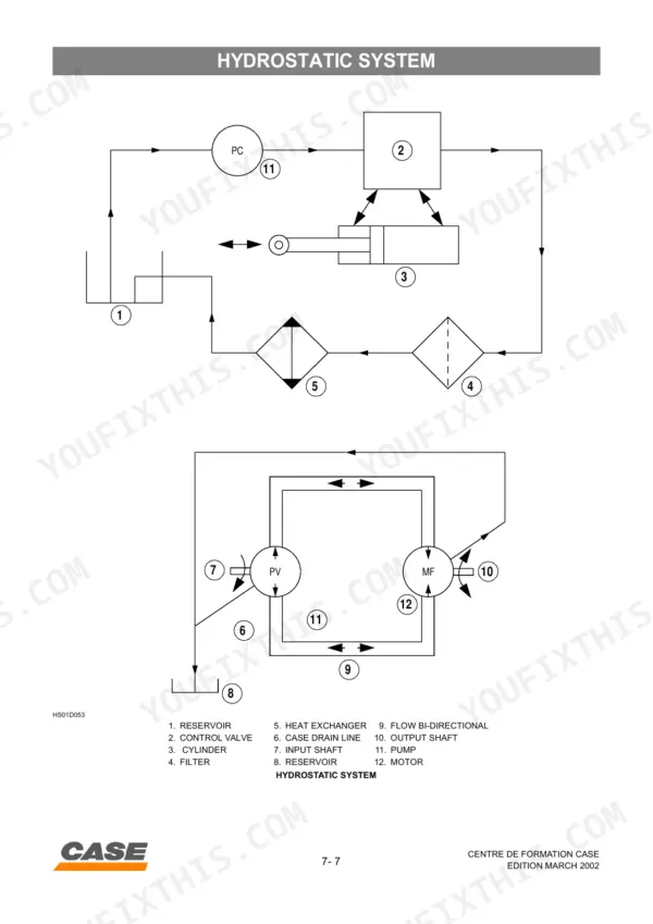
Start with the hydrostatic system general troubleshooting table to narrow down pump versus motor versus linkage. Check charge pressure and flow on the affected side against the good side using the checks; a charge pressure gap points to a worn hydrostatic pump. Verify the hydrostatic drive pump doesn't exceed its 345 kPa maximum pressure spec, and inspect the control linkage for a bent or disconnected rod.
Manual Section: Hydrostatic System General TroubleshootingReversible standard tires wearing unevenly and rubbing against the frame during turns
Check tire mounting direction and rotation pattern against the 12x16.5 tire dimension spec, since these reversible tires must be rotated on schedule to even out wear. Inspect the frame clearance area for scuffing that indicates the tire is riding too close, and check wheel bearing play. Re-torque wheel lug nuts to spec and confirm tire pressure matches the sidewall rating before returning the machine to service.
Manual Section: Presentation: Technical Specifications p. 10Frequently Asked Questions
How do you reset the hydraulic control valve on Case 40XT, 60XT, and 70XT skid steers?
The manual provides procedures for "Centering the servo piston" and "Hydraulic Neutral Adjustment" to address issues with the hydraulic control valve. Centering the servo piston involves connecting a hose between ports or removing a restriction orifice, then adjusting the servo screw until the tires begin to rotate in both directions, centering the screw between these points. The hydraulic neutral adjustment requires raising the unit, releasing brakes, and using a jumper wire for the seat switch, then adjusting the servo adjustment bracket based on tire rotation. p. 203
What is the purpose of the spring in the hydraulic control valve for Case XT series?
Springs in the hydraulic control valve serve several purposes, including maintaining the main spool in a closed position within the main relief valve, where a small spring force keeps it closed until oil pressure exceeds its setting. In circuit relief valves, a spring holds a poppet against a seat, requiring hydraulic force to open it. Additionally, a spring-centered mechanism in the hydrostatic pump's servo control system returns the servo control to a neutral position. p. 47
How do you reset the hydraulic control valve spring on Case 40XT?
To adjust the hydraulic control valve spring, specifically the servo piston centering spring, you need to remove the cap and external sealing nut, then the bolts retaining the servo piston cover. Rotate the piston end cover off the servo adjusting screw and then tighten or loosen the centering spring lock nut until all looseness is removed. The lock nut must be positioned just tight to the spring. p. 205
What is the fuel tank capacity for Case 40XT, 60XT, and 70XT skid steers?
The fuel tank capacity for these skid steers is 83.3 litres (22 U.S. gallons). It is recommended to fill the tank at the end of the daily operating period to prevent condensation. p. 12
Is this Case 40 XT manual a download or a disc?
You get a 214-page searchable PDF that downloads instantly after checkout. Open it on your laptop, tablet, or phone, and bring it right to the shop floor.
Are there any print restrictions on this Case 40 XT manual?
Yes. The PDF has no DRM restrictions, so print any page or section you need for your shop. Works with any standard printer.
Is the electrical system covered in this Case 40 XT Service Manual?
Yes, this Case 40 XT, 60 XT, 70 XT Service Manual includes complete electrical wiring diagrams, wire routing, and connector pinouts.

Reviews
There are no reviews yet.