
Part of the Case Repair Manuals.
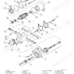
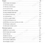
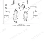
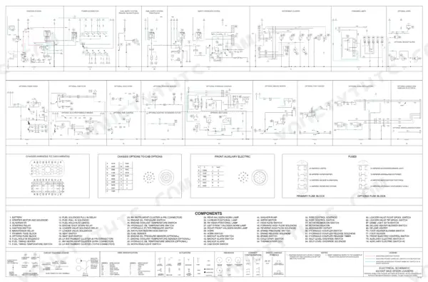
This 653-page Case 70XT Skid Steer Service Manual (OEM Bur 6-45720) puts every system on your machine under one cover, from the hydrostatic drive train to the loader and ROPS canopy. You get full wiring and hydraulic schematics in the rear pocket section, a dedicated electrical troubleshooting chapter, and step-by-step procedures covering engine removal, brake system rebuilds, and hydraulic component service. Inside: torque specs, fluid capacities, and maintenance interval charts pulled straight from Case engineering, not a forum thread. Set your main relief valve to 20,700 kPa (207 bar) and fill the tank to 83.3 litres, exactly what the factory calls for. Your hydrostatic system won't fix itself with guesswork. This PDF is bookmarked by section so you can jump from Power Train straight to Brakes without scrubbing through 650 pages, on your laptop in the office or your phone next to the machine.
Other edition of this manual
What's Inside This Case 60XT, 70XT, 60 Manual
| System | Pages | Key Topics |
|---|---|---|
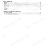
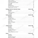
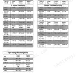
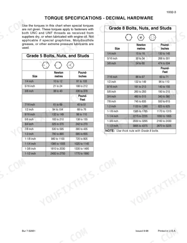
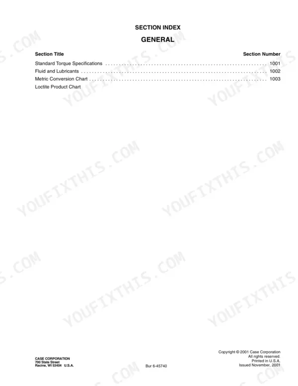
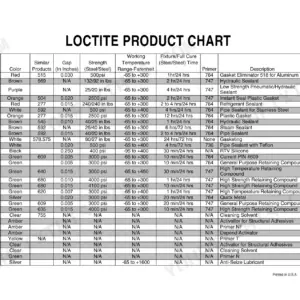
| General | 3-24 | Section Index - General, Fluids and Lubricants, Standard Torque Specifications, Metric Conversion Chart, Loctite Product Chart |
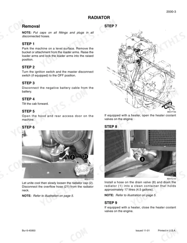
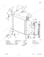
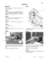
| Engine | 25-40 | Section Index - Engines, Engine and Radiator Removal and Installation |
| Fuel System | 41-42 | Section Index - Fuel Systems |
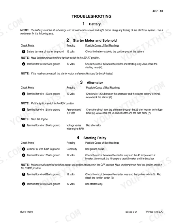
| Electrical System | 43-148 | Section Index - Electrical, Electrical System - How It Works, Electrical Specifications and Troubleshooting, Battery, Starter and Starter Solenoid, Alternator |
| Power Train | 149-280 | Section Index - Power Train, Hydrostatic System - How It Works, Hydrostatic System Troubleshooting, Removal and Installation of Hydrostatic Components, Drive Coupling, Piston Pump |
| Brakes | 281-342 | Section Index - Brakes, Brake System - How It Works, Brake System Troubleshooting, Removal and Installation of Park Brakes |
| Hydraulics | 343-566 | Section Index - Hydraulics, Hydraulic System - How It Works, Hydraulic System Troubleshooting, Cleaning the Hydraulic System and Hydrostatic System |
| Mounted Equipment | 567-650 | Section Index - Mounted Equipment, Pedals and Levers, Loader, Attachment Coupler, ROPS Canopy, Seat, Seat Belts, And Operators Compartment |
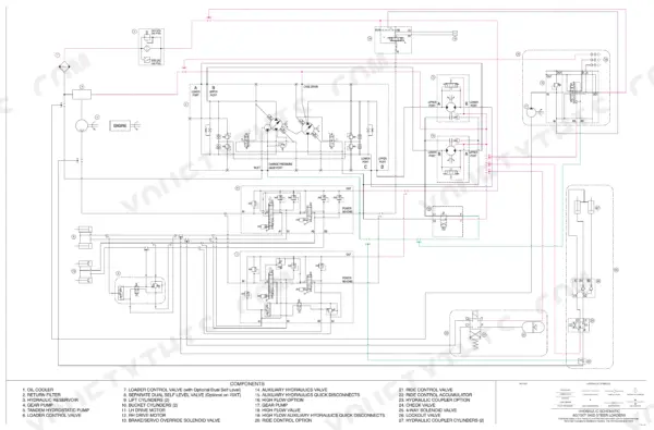
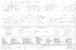
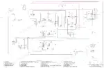
| Schematic Set | 651-653 | Hydraulic and Electrical Schematics |
Quick Reference Specifications
| Specification | Value | Page |
|---|---|---|
| Main Relief Pressure | 20,700 kPa (207 bar) (3000 psi) | p. 393 |
| Control handle to ROPS front post clearance | 25 to 40 mm (0.98 to 1.57 inches) | p. 579 |
| Auxiliary hydraulic pedal position | Adjust the cable until the auxiliary hydraulic pedal is in the horizontal position. | p. 584 |
| Fuel Tank Capacity | 83.3 litres (22 U.S. gallons) | p. 7 |
| Engine Crankcase Oil Capacity - with filter change | 10.4 litres (11.0 quarts) | p. 7 |
| Hydrostatic Pump System Relief Pressure (forward and reverse) | 34,500 kPa (5004 psi) | p. 179 |
| Hydrostatic Drive Motors Maximum Displacement | 503 cc (30.7 in³) | p. 179 |
| Tandem Pump Mounting Bolts Torque | 102 to 113 Nm (75 to 83 pound-feet) | p. 187 |
| Nuts for Wheels Torque | 135 to 163 Nm (100 to 120 pound-feet) | p. 263 |
| Brake System Release Pressure (Maximum) Fully Disengaged | 1034 kPa (10.34 bar) (400 psi) | p. 293 |
| Loader Control Valve Main Relief Pressure | 20,700 kPa (207 bar) (3000 psi) | p. 393 |
| Loader Raising Time (with rated load in bucket) | 4.1 seconds | p. 393 |