
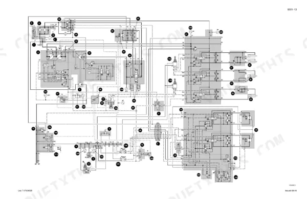
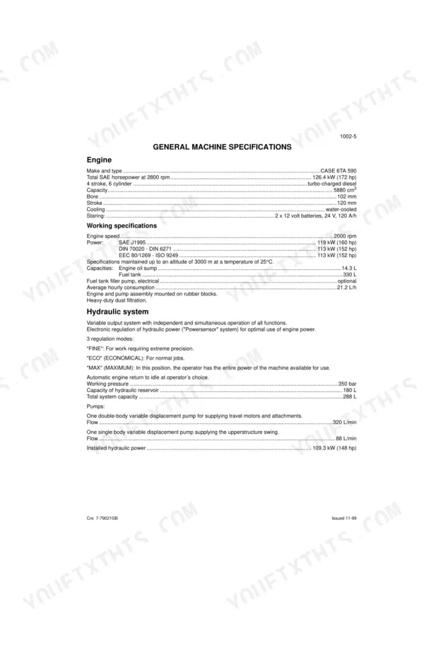
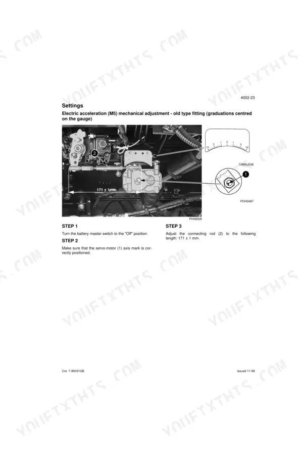
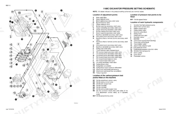
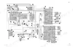
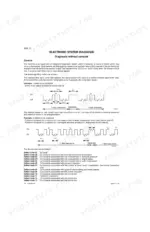
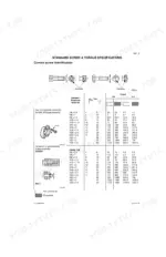
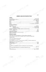
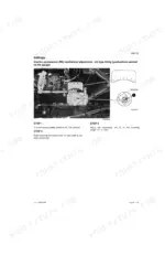
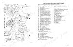
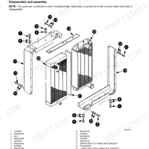
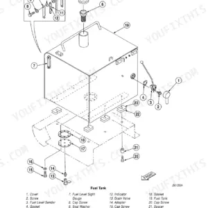
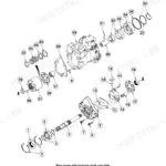
Part of the Case Schematics.
This 318-page Case 1188 Service Manual (OEM Cre 7-57691GB) covers the 1188 Crawler and Wheeled Excavators, and it doesn't split the difference between them, each system gets its own dedicated coverage. Inside you get full electrical schematics for old and new version cabinets on both crawler and wheeled configurations, plus hydraulic schematics for mono-speed and two-speed setups. A full electronic troubleshooting section walks you through diagnosis and settings before you start pulling connectors. Set the main relief valve between 395 and 415 bar, and torque the engine speed detector lock-nut to 10 Nm, real numbers pulled straight from the factory pages, not a forum thread. No more guessing which wiring version your cabinet actually has. The PDF carries bookmarks for every section, so you jump straight from cover to hydraulic schematic without hunting through 318 pages by hand.
What's Inside This Case 1188, 1188 Plus Manual
| System | Pages | Key Topics |
|---|---|---|
| Safety, General Information and Torque Specifications | 3-14 | Safety, Twin Wheels, General Information, Correct Use of Torque Wrenches, Hardware Tightening Order, Standard Screw a Torque Specifications, Metal Cap References |
| Specifications - Crawler Excavators | 15-42 | Crawler Excavator, Track and Undercarriage Configuration, Machine Overall Dimensions, Transportation Overall Dimensions, General Machine Specifications, Weights, Fluids and Lubricants, Summary of Detailed Specifications per Component |
| Specifications - Wheeled Excavators | 43-72 | Wheeled Excavator, Tyres, Axles and Road Travel Configuration, Machine Overall Dimensions, Transportation Overall Dimensions, General Machine Specifications, Weights, Fluids and Lubricants, Summary of Detailed Specifications per Component |
| Electrical Schematics - Crawler Excavators (Old and New Versions) | 73-144 | Crawler Excavator, Track and Undercarriage Configuration, Specifications, Schematic Symbols, Description of Electrical Cabinet Printed Circuit (Standard Equipment), Description of Electrical Cabinet Printed Circuit (Optional Equipment), Description of Electrical Cabinet Printed Circuit (Standard), Description of Electrical Cabinet Printed Circuit (Optional) |
| Electrical Schematics - Wheeled Excavators (Old and New Versions) | 145-230 | Wheeled Excavator, Tyres, Axles and Road Travel Configuration, Specifications, Schematic Symbols, Description of Electrical Cabinet Printed Circuit (Standard), Description of Electrical Cabinet Printed Circuit (Optional) |
| Electronic and Troubleshooting System - Crawler Excavators | 231-258 | Crawler Excavator, Track and Undercarriage Configuration, Tools Required, Electronic System, Electronic System Diagnosis, Settings, Electric Acceleration Mechanical Adjustment - New Type Fitting (Graduations Offset 15° on the Gauge) |
| Electronic and Troubleshooting System - Wheeled Excavators | 259-286 | Wheeled Excavator, Tyres, Axles and Road Travel Configuration, Tools Required, Electronic System, Electronic System Diagnosis, Settings, Electric Acceleration Mechanical Adjustment - New Type Fitting (Graduations Offset 15° on the Gauge) |
| Hydraulic Checks, Adjustments and Schematics - Crawler Excavators | 287-302 | Crawler Excavator, Track and Undercarriage Configuration, Tools Required, Tools to Be Made, Pressure Setting Schematic, Pressure Setting, Hydraulic Schematic (Mono-Speed), Hydraulic Schematic (Two-Speed) |
| Hydraulic Checks, Adjustments and Schematics - Wheeled Excavators | 303-318 | Wheeled Excavator, Tyres, Axles and Road Travel Configuration, Tools Required, Tools to Be Made, Pressure Setting Schematic, Pressure Setting, Hydraulic Schematic |
Quick Reference Specifications
| Specification | Value | Page |
|---|---|---|
| 1188 Crawler Excavators | ||
| Main relief valve pressure setting | 395 to 415 bar | p. 32 |
| Engine speed detector lock-nut torque | 10 Nm | p. 258 |
| Boom Cylinders Weight (per cylinder) | 145 or 155 kg | p. 33 |
| 1188 Wheeled Excavators | ||
| Main relief valve pressure setting | 395 to 415 bar | p. 64 |
| Engine speed detector lock-nut torque | 10 Nm | p. 286 |
| All Models | ||
| Engine Capacity | 5880 cm3 | p. 19 |
| Hydraulic System Working Pressure | 350 bar | p. 19 |
| Hydraulic Reservoir Capacity | 180 L | p. 19 |
| Main Pump Flow | 320 L/min | p. 19 |
| Inside Operator's Compartment Noise Level (LpA) | 79 dB(A) | p. 22 |
| Track Pad Screw Torque | 510 to 570 Nm | p. 39 |
Case 1188, 1188 Plus Common Problems This Manual Covers
Case 1188 hydraulic pressure warning light on, sensor fault suspected after rebuild
Check the B11 pressure sensor connections and cable condition per the defect code 03 procedure on page 243. Verify hydraulic system working pressure reads at 350 bar with the engine at operating temperature. If the sensor cable shows corrosion or the connector is loose, replace the sensor rather than attempting a repair splice.
Manual Section: Electronic System Diagnosis (1188 Crawler Excavators) p. 243Needle bearings wearing out fast within weeks of a hydraulic pump teardown
Never dry bearings with compressed air; spinning them unlubricated pits the races in seconds. Wipe them down with a lint-free rag and coat immediately with clean hydraulic oil. Check the bore edge for metal particles or misalignment before reinstalling, and confirm rotation is smooth and free of drag prior to final assembly.
Manual Section: Safety, General Information and Torque Specifications p. 5Engine won't seat right during reinstall, components still hot to the touch
Disconnect the battery first and let the engine cool fully before pulling access panels; skipping this step is what causes misalignment and burned hands during reinstall. Follow the tightening order and torque specifications on page 11 for mounting hardware. Confirm all sensor and solenoid connectors are reseated before cranking.
Manual Section: Safety, General Information and Torque Specifications p. 11Deep pitting and scratches found on hydraulic components during teardown
Inspect every hydraulic part visually before reuse; scratches or pitting on mating surfaces will deepen into leak paths under 350 bar working pressure. Cross-reference the hydraulic schematic on page 299 to confirm which line or valve body you're pulling. Replace any component with visible scoring rather than reinstalling it.
Manual Section: Hydraulic Checks, Adjustments and Schematics - 1188 Crawler Excavators p. 299Engine speed detector reading erratic or dropping out intermittently
Check the B9 speed detector wiring and connector for corrosion. Torque the lock-nut to 10 Nm, no more, overtightening cracks the sensor housing and causes the same intermittent dropout you're chasing. Verify the sensor gap and rerun calibration once reseated.
Manual Section: Electronic and Troubleshooting System - 1188 Crawler Excavators p. 258Main relief valve won't hold setting, pressure drifts down under load
Set the main relief valve to 395 to 415 bar per the pressure setting procedure on page 292. Confirm the pilot pressure and load sensing valve are in spec before adjusting the relief valve itself, a bad pilot signal will make a good relief valve look faulty. Recheck after a full warm-up cycle since cold oil reads low.
Manual Section: Hydraulic Checks, Adjustments and Schematics - 1188 Crawler Excavators p. 292Frequently Asked Questions
How do I reset an error code on the Case 1188 excavator?
The manual indicates that after each corrective action during troubleshooting, the system should be reset by switching the machine off and on again. This is a general instruction provided at the end of several troubleshooting flowcharts for various defect codes, ensuring the system reinitializes after a repair. p. 242
What are the torque specifications for engine bolts on the Case 1188 crawler excavator?
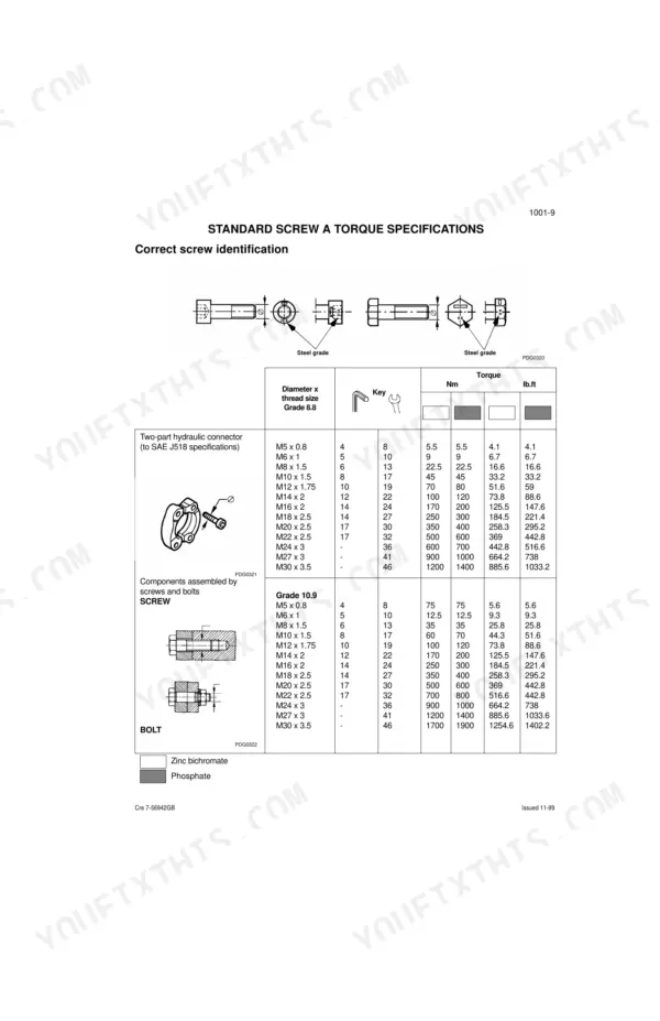
The manual provides general torque specifications for standard screws and bolts, categorized by diameter, thread size, and grade (8.8 or 10.9). For example, an M10 x 1.5 Grade 8.8 screw requires 45 Nm (33.2 lb.ft) of torque, while an M10 x 1.5 Grade 10.9 screw requires 60 Nm (44.3 lb.ft). Specific torque values for engine bolts are not explicitly listed. p. 11
What are the common error codes for the Case 1188 hydraulic excavator?
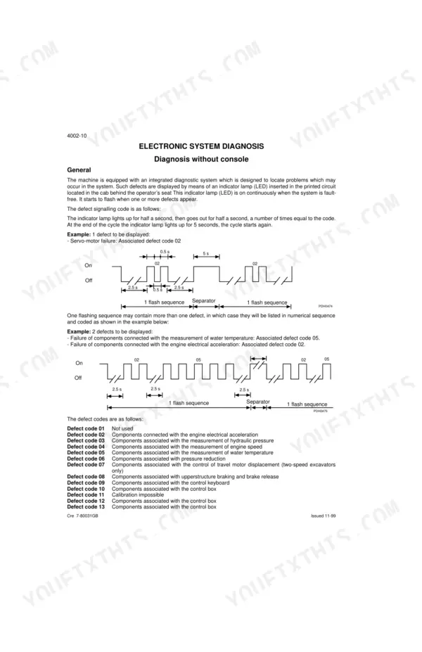
The manual lists several defect codes for the electronic system. For example, Defect code 02 is for components associated with engine electrical acceleration, Defect code 03 is for components associated with the measurement of hydraulic pressure (L.S.), and Defect code 04 is for components associated with the measurement of engine speed. These codes help diagnose specific issues within the machine's electronic functions. p. 240
How do I reset the hydraulic system pressure on the Case 1188?
To adjust hydraulic system pressures on the Case 1188, specific procedures are outlined. For instance, the pilot pressure should be between 34 and 38 bar, and the main relief valve (A) is adjusted by feeding the bucket function with no spacer on the push rod until the same pressure is obtained as on the bucket safety valve. These are adjustment procedures, not a simple reset. p. 293
What do I get after purchasing this Case 1188 Crawler Excavators?
A 318-page Service Manual in searchable PDF format, available the moment you complete checkout. View on computer, tablet, or phone, with no shipping wait.
Are there any print restrictions on this Case 1188 Crawler?
Yes, print as many copies as you want, and there are no restrictions. Many mechanics print the section they need and bring it to the shop floor.
Does this Case 1188 Crawler Excavators manual have electrical?
Yes, this Case 1188 Crawler Excavators Service Manual includes complete electrical wiring diagrams, wire routing, and connector pinouts.

Reviews
There are no reviews yet.