Part of the Case Repair Manuals.
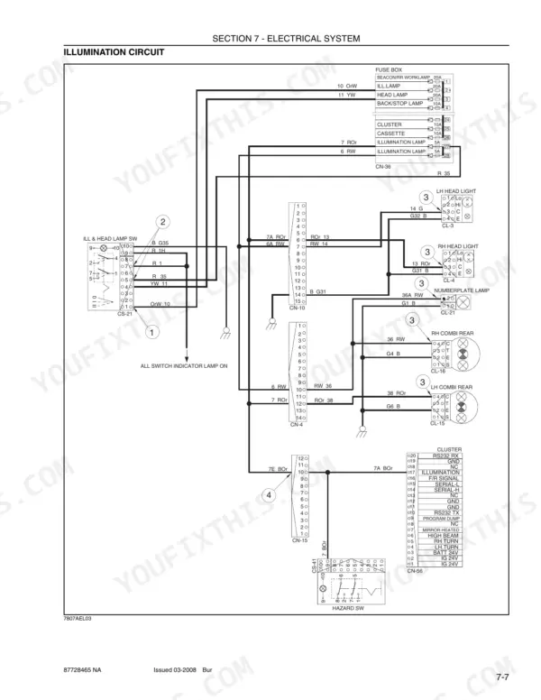
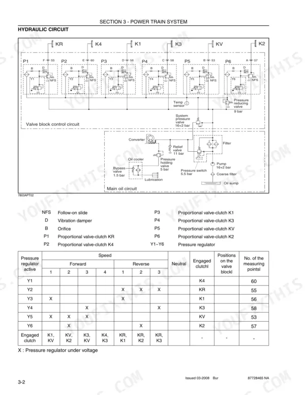
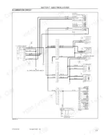
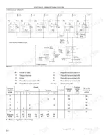
Power train, brakes, steering, work equipment and the full electrical system: the Case 1221E repair manual PDF walks each one end to end across 534 pages, issued as OEM 87728465 NA for the 1221E wheel loader. Wiring diagrams trace circuits from the electronic monitor system back through the switches and connector faces, so a dead gauge becomes a pin to probe instead of a harness to replace. Hydraulic schematics follow flow through the main control valve out to the bucket cylinders, and the power train section claims the longest run of the book, from structure and function through operational checks, tests and adjustments, and complete disassembly and assembly. Your battery pair is rated 2x12V x 200Ah; tire mounting nuts pull to 48.5 plus or minus 2.5 kgf.m, main control valve mounting bolts to 12.8 plus or minus 3.0 kgf.m. Bookmarked and searchable by keyword, it downloads once and stays yours as long as the loader does.
What's Inside This Case 1221E Repair Manual
| System | Pages | Key Topics |
|---|---|---|
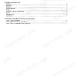
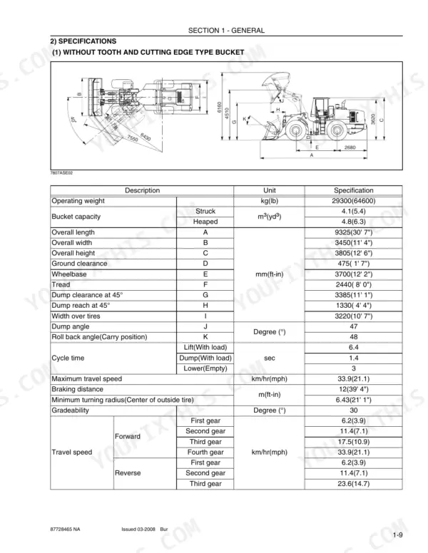
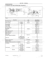
| General | 1-36 | Safety Hints, Specification, Operational Checkout Record Sheet |
| Engine | 37-48 | Structure and Function |
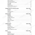
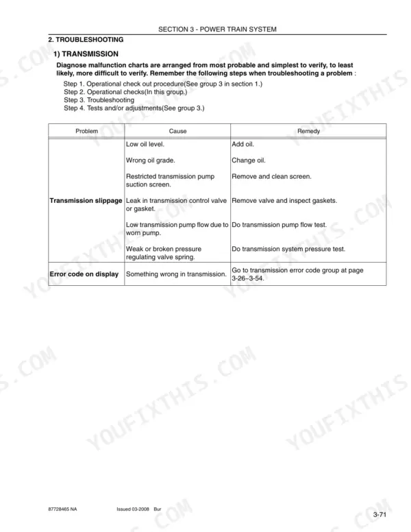
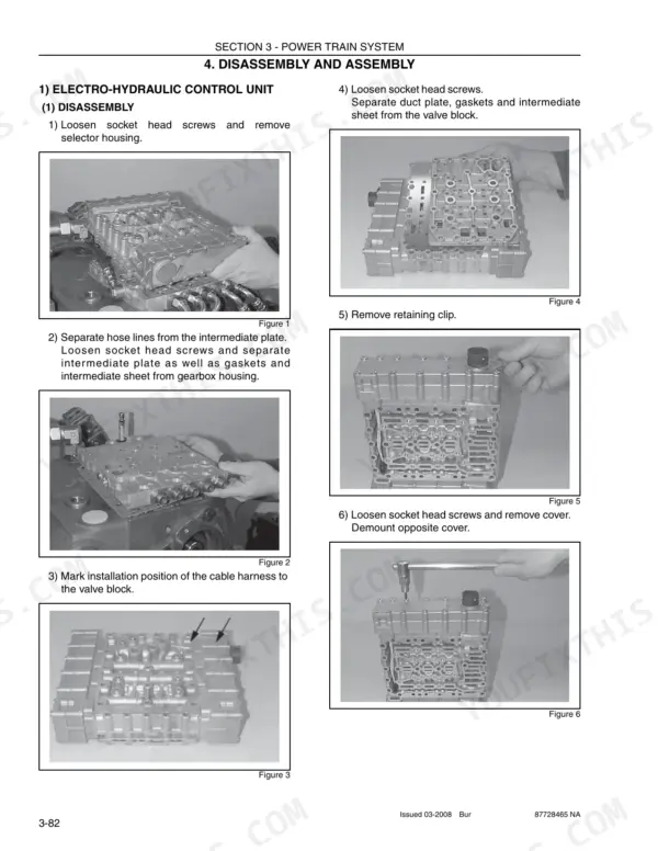
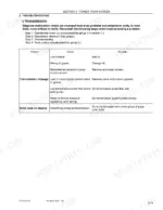
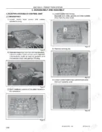
| Power Train System | 49-260 | Structure and Function, Operational Checks and Troubleshooting, Tests and Adjustments, Disassembly and Assembly |
| Brake System | 261-288 | Structure and Function, Operational Checks and Troubleshooting, Tests and Adjustments |
| Steering System | 289-372 | Structure and Function, Operational Checks and Troubleshooting, Tests and Adjustments, Disassembly and Assembly |
| Work Equipment | 373-448 | Structure and Function, Operational Checks and Troubleshooting, Tests and Adjustments, Disassembly and Assembly |
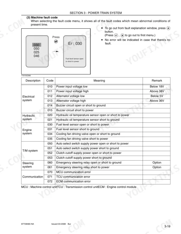
| Electrical System | 449-534 | Component Location, Electronic Monitor System, Switches, Electrical Component Specification, Connectors, Troubleshooting |
Quick Reference Specifications
| Specification | Value | Page |
|---|---|---|
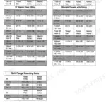
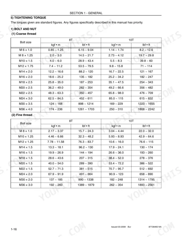
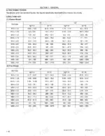
| Tire mounting nut | 48.5 ± 2.5 kgf • m | p. 32 |
| Pipe and hose (Orfs type) 13/16-16" thread | 4.4 kgf • m | p. 31 |
| Max. tightening torque for 1/4 BSP.F | 4.1 kgf·m (29.7 lbf·ft) with cutting edge, 2.0 kgf·m (14.5 lbf·ft) with copper washer, 3.1 kgf·m (22.4 lbf·ft) with aluminum washer | p. 350 |
| Battery | 2×12V×200Ah | p. 27 |
| Main control valve mounting bolt | 12.8 ± 3.0 kgf • m | p. 32 |
| Transmission bolt, nut(Rubber, 4EA) | 100 ± 15.0 kgf • m | p. 32 |
| Transmission bolt(Converter cover, 4EA) | 18.4 ± 2.0 kgf • m | p. 32 |
| Overload relief valve pressure(Boom) | 240kgf/cm²(3414psi) | p. 14 |
| Main pump maximum operating pressure | 210kgf/cm²(2987psi) | p. 14 |
| Steering pump maximum operating pressure | 210kgf/cm²(2987psi) | p. 14 |
| Clutch cut-off pressure switch rated pressure | 25 kgf/cm² | p. 129 |