


Part of the Case IH Repair Manuals.
Every mechanic working on a Case IH 384 tractor chassis eventually needs the factory service manual pdf. This 190-page OEM document (GSS-1489) goes system by system from cab and sheet metal through the Power Take-Off, with nothing left out. Open to the electrical section for complete wiring diagrams: alternator, safety start switch, and full lighting circuit. Packed with hydraulic schematics, exploded views across transmission and rear axle assembly, a full torque table section, and step-by-step procedures for dual clutch dismantling, differential removal, and draft control. Torque the dual clutch flywheel bolts to 9.0-9.7 kgm (65-70 lb-ft); clutch pedal bolts spec at 4.9-5.5 kgm (35-40 lb-ft). No more second-guessing expensive fasteners. Bookmarked and searchable; open it on your tablet, jump straight to the system you need, and get back to work.
What's Inside This Case IH 384, 384 Chassis Manual
| System | Pages | Key Topics |
|---|---|---|
| Work Safely - Follow These Rules | 6-8 | To Prevent Injury, Always Use Safety Stands, Always Wear Safety Glasses, Keep Work Area Organized and Clean, Reinstall Safety Devices |
| General | 9-20 | Service Tools, Service Parts, Serial Numbers, Adjustment, Inspection and Repair, Specifications |
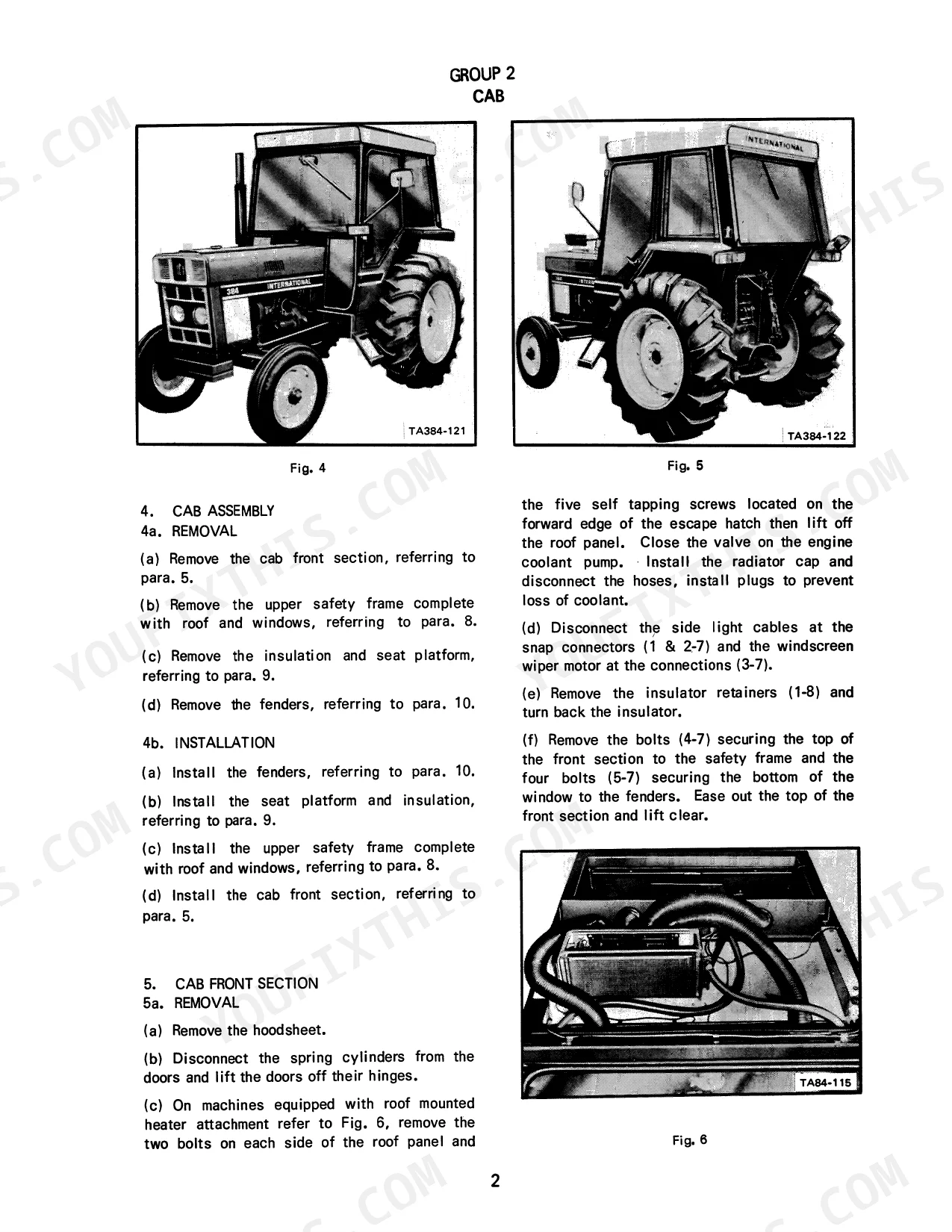
| Cab and Sheet Metal | 21-34 | Hoodsheet, Grille Support, Cab Assembly, Cab Front Section, Side Windows, Rear Window, Upper Safety Frame, Insulation and Seat Platform |
| Cooling System | 35-37 | Radiator Removal, Dismantling, Inspection, Assembly, Installation |
| Electrical and Instruments | 38-46 | Battery, Alternator, Starting Motor, Safety Start Switch, Brake Light Switch, Headlights, Side Lights, Stop |
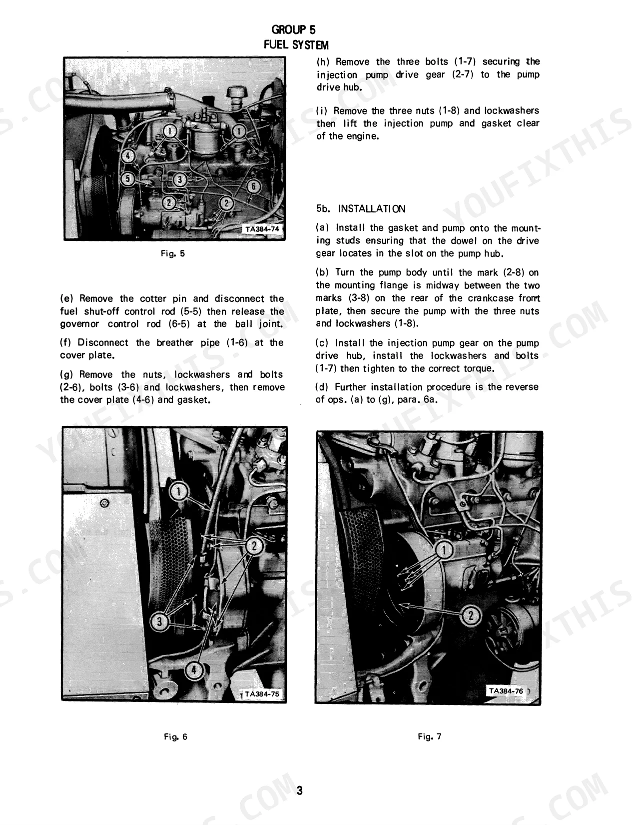
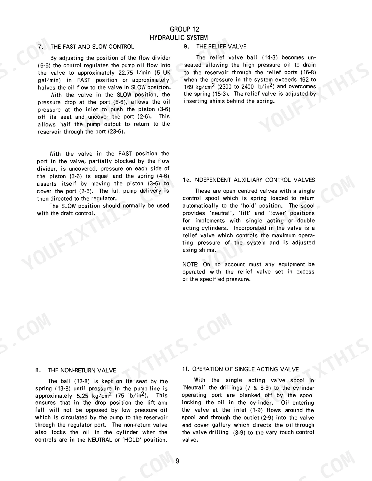
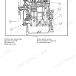
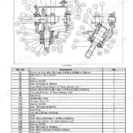
| Fuel System | 47-53 | Fuel Tank, Lift Pump, Fuel Filter, Injection Pump, Injectors, Governor Control Linkage |
| Engine | 54-57 | Air Cleaner Removal, Air Cleaner Installation, Engine Removal, Engine Installation |
| Engine Clutch | 58-67 | Single Plate and Heavy Duty Clutch, Dual Clutch, Engine Clutch Removal, Single Plate Clutch Dismantling, Dual Clutch Dismantling, Cleaning and Inspection |
| Transmission | 68-91 | Gearbox Top Cover, Driving Shaft, Standard P.T.O., Constant Running P.T.O., Pinion Shaft, Countershaft |
| Rear Axle and Differential | 92-100 | Rear Axles Removal, Rear Axles Dismantling, Assembly, Installation, Adjustments, Differential Removal, Bull Pinion Shaft Bearing Cages Dismantling |
| Brakes | 101-107 | Disc Brakes, Brake Cross Shaft, Brake Pedal Locking Lever, Over-Centre Type, Ratchet Type |
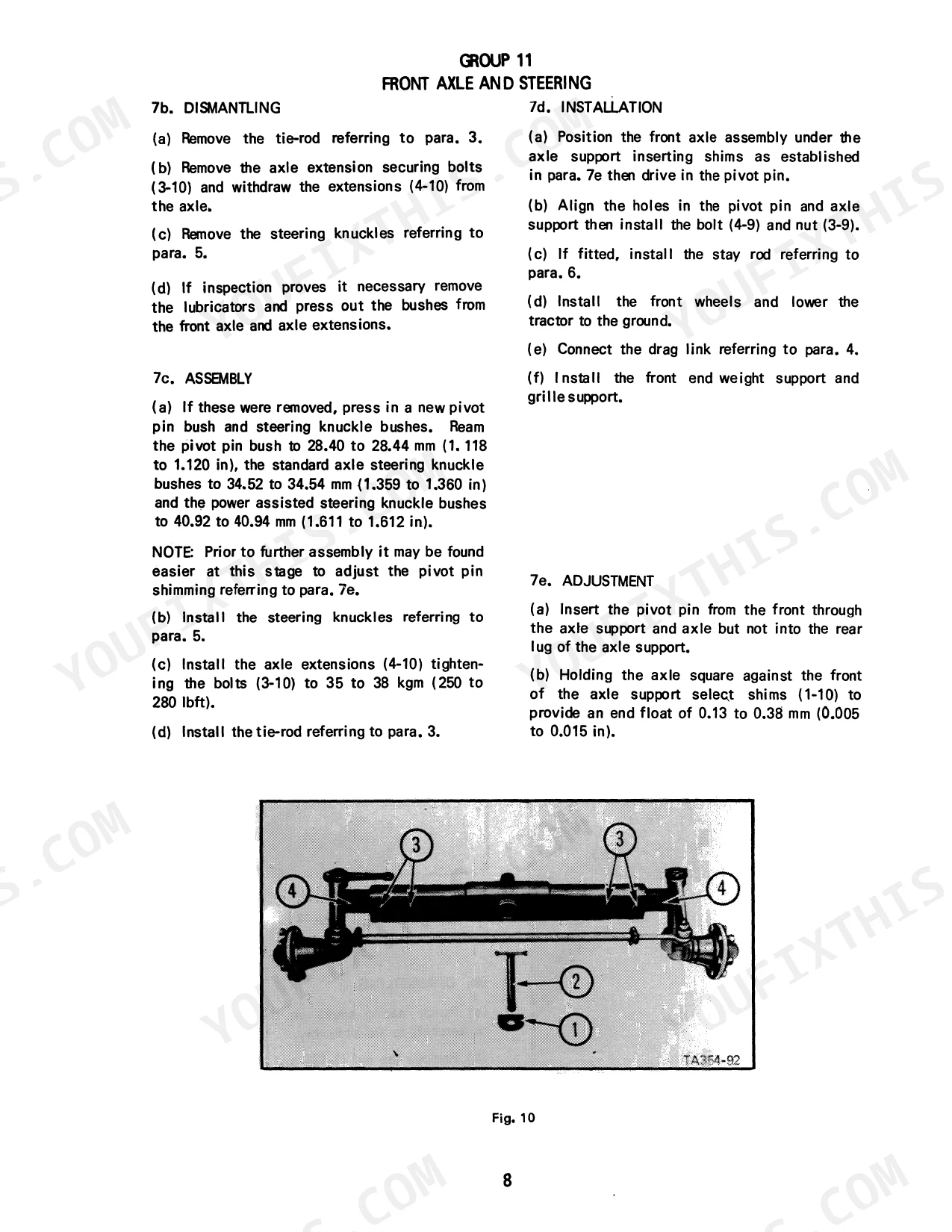
| Front Axle and Steering | 108-130 | Front Hubs, Tie Rod, Drag Link, Steering Knuckles, Axle Stay Rod, Front Axle, Front Axle Support, Steering Box |
| Hydraulic System | 131-168 | Hydraulic Pump, Hydraulic/Steering Pump, Lift Housing, Quadrant, Cylinder Head, Control Valve Assembly, Rockshaft, Draft Control |
| Power Take-Off and Belt Pulley | 169-190 | P.T.O. Rear Shaft and P.T.O. Lever, Clutch Housing, Single Speed Constant Running P.T.O., Dual Speed Constant Running P.T.O., Constant Running P.T.O. with F/R, Belt Pulley |
Quick Reference Specifications
| Specification | Value | Page |
|---|---|---|
| Dual Clutch Pedal bolts torque | 4.9 to 5.5 kgm (35 to 40 lbft) | p. 9 |
| Dual Clutch Flywheel bolts torque | 9.0 to 9.7 kgm (65 to 70 lbft) | p. 9 |
| Engine Number of cylinders | 4 | p. 16 |
| Engine Clutch Single Plate Pedal Settings Height from footplate | 177 mm | p. 16 |
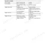
Case IH 384, 384 Chassis Common Problems This Manual Covers
Case IH 384 clutch slipping and engine roaring while brakes are applied.
Remove the engine clutch components following page 58. Inspect the single plate and heavy-duty clutch assemblies for excessive wear. During reassembly, torque the flywheel bolts to 65 to 70 lbft (9.0 to 9.7 kgm) as detailed on page 9 to prevent future slippage.
Manual Section: Engine Clutch p. 58Loose clutch pedal feeling and failure to engage gears properly during operation.
Adjust the single plate pedal settings to fix engagement issues. Measure the height from the footplate and set the linkage to exactly 177 mm as required on page 16. Torque the dual clutch pedal bolts to 35 to 40 lbft (4.9 to 5.5 kgm) per page 9.
Manual Section: General p. 16Engine misfires or runs extremely rough when pulling implements under heavy load.
Inspect the fuel system starting on page 47. Bleed the injection pump and verify uniform fuel delivery to all 4 cylinders. Check the fuel filter and lift pump for restrictions, and adjust the governor control linkage to maintain steady RPM during operation.
Manual Section: Fuel System p. 47Frequently Asked Questions
Torque specs for the engine bolts?
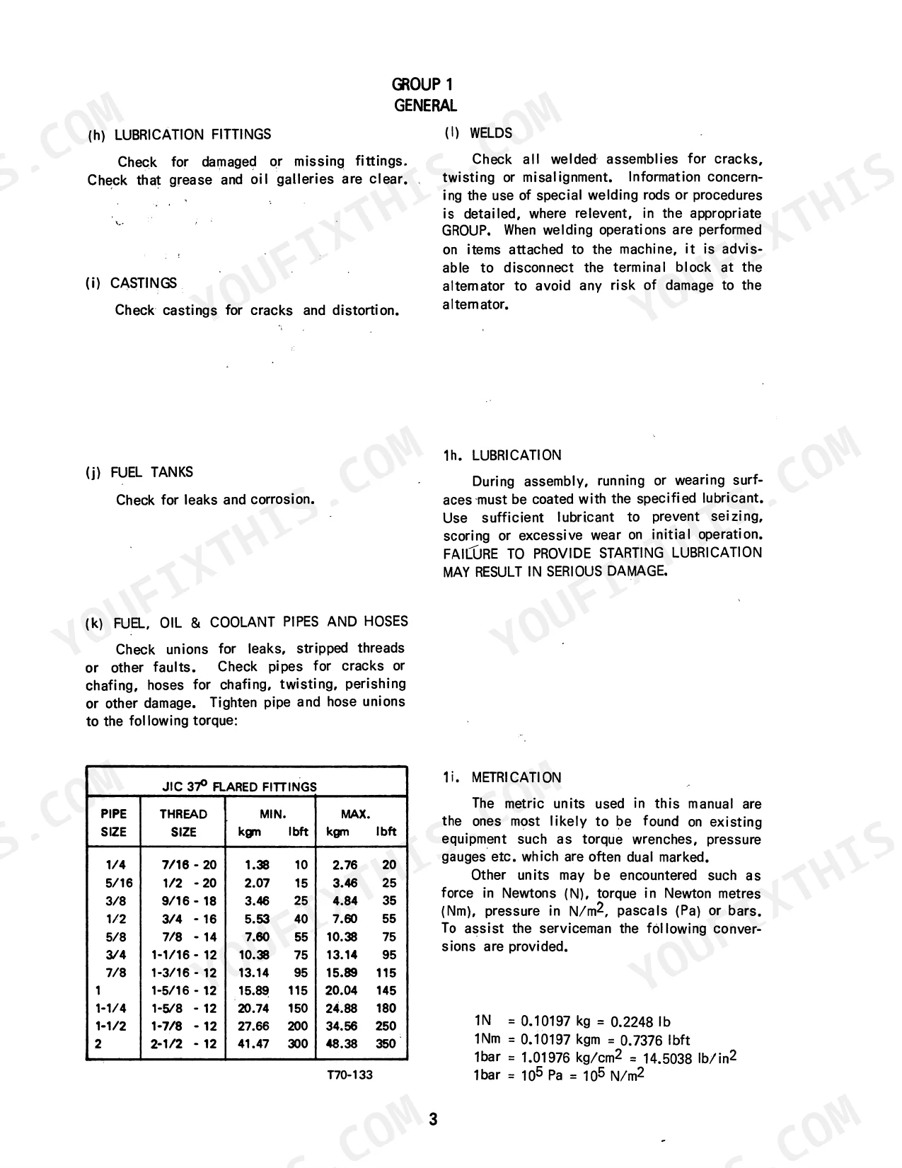
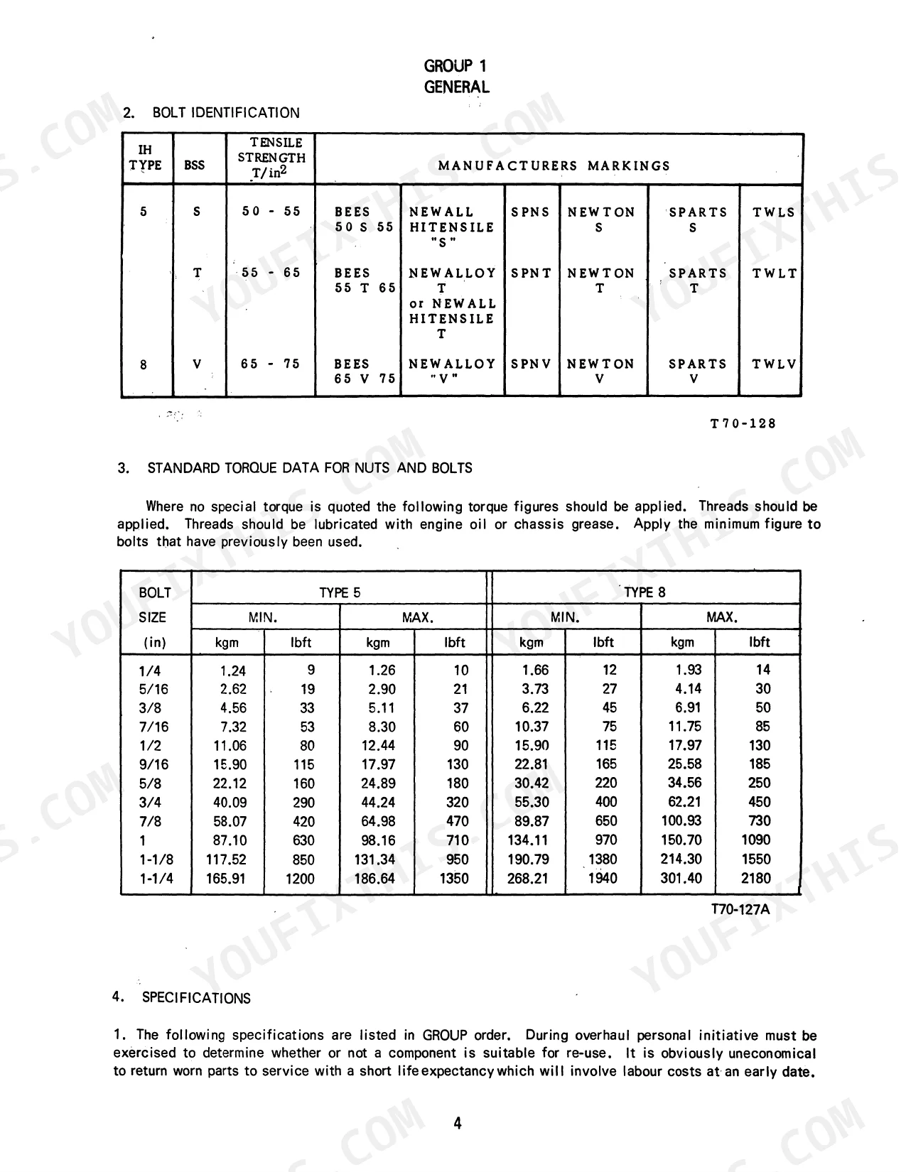
The manual provides standard torque data for nuts and bolts on page 13, to be applied where no special torque is quoted. For example, a 1/4 inch Type 5 bolt requires 1.24 kgm (9 lbft) minimum torque, while a 1 inch Type 8 bolt requires 134.11 kgm (970 lbft) minimum torque. These values are dependent on bolt size and type and should be used unless specific torque is mentioned for engine bolts. p. 13
What format is this Case IH 384, 384 Tractor, 384 Tractor Chassis, 384?
Instant PDF download (46 MB). You get the full 190-page searchable Service Manual immediately after payment. Open it on your laptop, tablet, or phone right in the shop.
Is this Case IH 384, 384 Tractor, 384 Tractor Chassis, 384 TRACTORS manual?
Yes, print as many copies as you want, and there are no restrictions. Many mechanics print the section they need and bring it to the shop floor.
Does this Case IH 384, 384 Tractor, 384 Tractor Chassis, 384 TRACTORS manual?
Yes. The manual includes hydraulic circuit diagrams, system schematics, and component specifications with pressure ratings.


Reviews
There are no reviews yet.