


Part of the Case IH Repair Manuals.
All 155 pages of this Case IH Magnum 180, 190, and 210 service manual (OEM #84202702) focus on one engine: the F4HE NEF Tier 3 six-cylinder that keeps your tractor pulling through a full season of field hours. You get full wiring diagrams for the EDC7 electronic injection system, pinout references for every sensor connector on the engine harness, fault codes, and a troubleshooting section that walks through the Common Rail system from CP3 high-pressure pump to rail to electro-injectors. Open to the overhaul section: exploded views, clearance data, and rebuild procedures for the cylinder unit, timing system, output shaft, and connecting rod-piston assembly are all here. Torque the M18 nut on your high-pressure pump gear to 105 ± 5 Nm, then confirm the overheating protection threshold at 110 °C: both straight from factory data. Your NEF is down and the dealer wants a week. Pull it up on any device, jump by bookmark to the section you need, and get the teardown started.
What's Inside This Case IH Magnum 180-210 (NEF) Manual
| System | Pages | Key Topics |
|---|---|---|
| Cylinder 6.7L Nef Tier 3 Engine for Magnum 180, 190 and 210 Tractors Service | 1 | General Specifications, Fuel, Duty - Industrial Application, Overhaul and Technical Specifications, Tools, Safety Prescriptions |
| Symbols -Warnings | 2 | Danger for Persons, Danger of Serious Damage for the Assembly, General Danger, Environment Protection |
| General Warnings | 3-4 | Warnings Shown Cannot Be Representative, Use Both Specific and General-Purpose Toolings, Manual Handling of Loads, Handling by Mechanical Means, In Disassembling Operations |
| General Warnings on the Electric System | 5 | If an Intervention Has to Be Made, Before Connecting the Batteries, Disconnect the External Recharging Apparatus, Do Not Cause Sparks, Do Not Use a Test Lamp |
| Optional Electrical and Mechanical Parts Installations | 6 | Assemblies Shall Be Modified and Equipped, It Is Reminded That, Especially About the Electric System, It Is Absolutely Forbidden to Make Modifications |
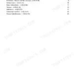
| Conversions Between the Main Units of Measurement of Theinternational System and | 7 | Power, Torque, Revolutions per Time Unit, Pressure, Temperature |
| Nef Tier 3 Engines | 8-9 | Nef Tier 3 Engine Family Introduction, F4HE Six-Cylinder Diesel Coverage, Multiple Duty Variants (F4CE, F4DE, F4GE), Tier 3 Emission Compliance, Common Rail EDC7 System Overview |
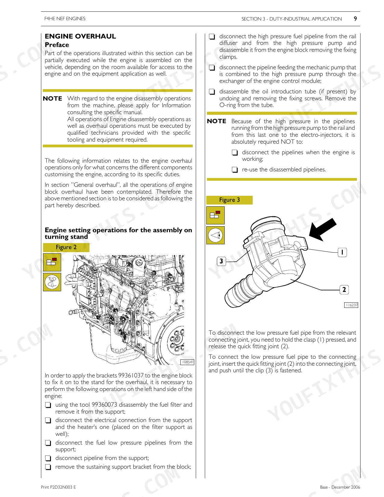
| F4He Nef Engines | 10-11 | Nef Engine Architecture and Working Principle, High-Pressure Common Rail Fuel Feed, Wiring Harness and Electronic Control Units, Mechanical Overhaul and Bench Operations, Troubleshooting and Fault Diagnosis Procedures |
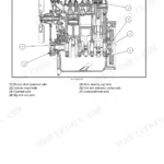
| Special Remarks | 12 | Diagrams and Symbols Usage, Example (Housing for Connecting Rod Small End Bush, Housing for Connecting Rod Bearings, Tighten to Torque, Tighten to Torque + Angular Value) |
| Symbols - Assistance Operations | 13 | Removal, Disconnection, Refitting, Connection, Tighten to Torque, Measurement, Value to Find, Check |
| Updating | 14-15 | Duty-Industrial Application, Overhaul And Technical Specifications, Tools |
| General Specifications | 16-27 | Correspondence Between Technical Code and Commercial Code, Lubrication (4-Cylinder Engine Version, 6-Cylinder Engine Version) |
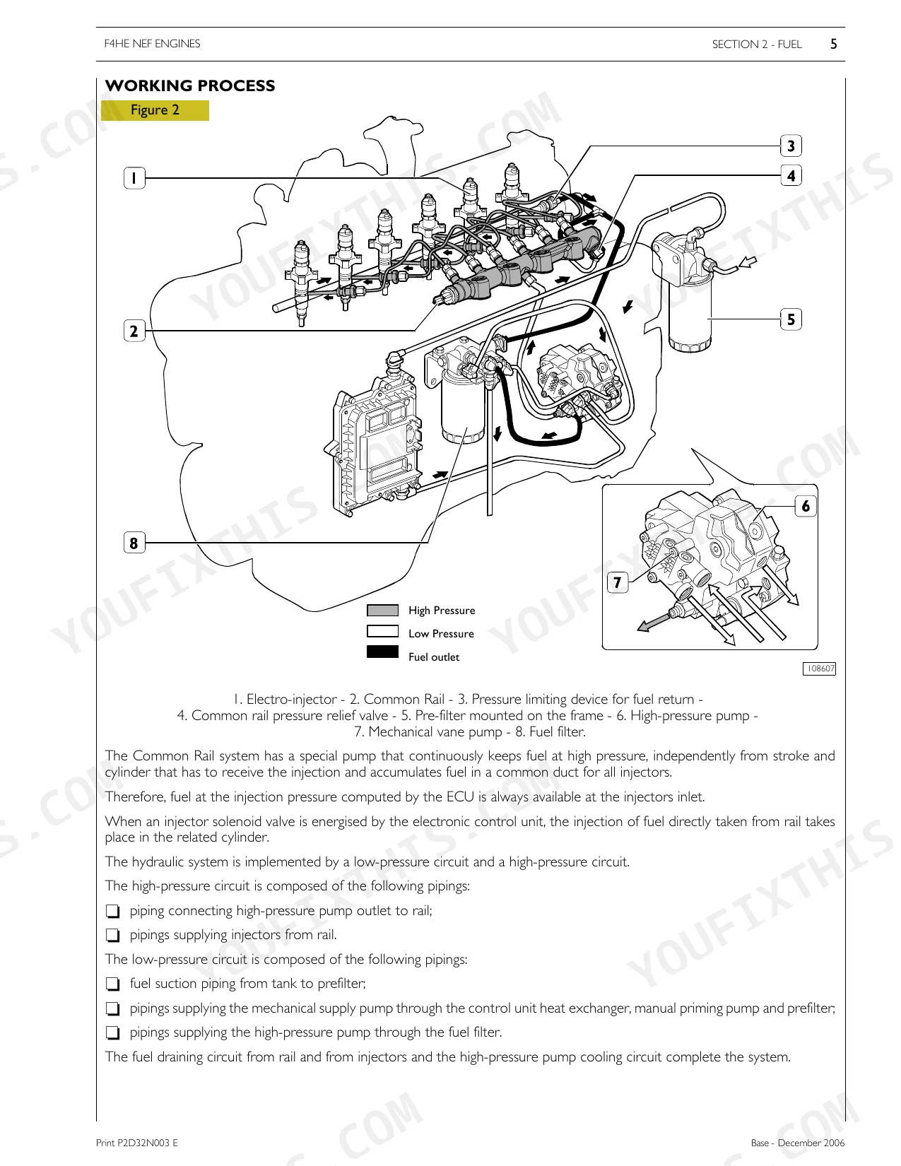
| Fuel | 28-41 | High Pressure Electronic Injection System, Edc 7 Operation, Working Process, Fuel System Layout, Mechanical Feeding Pump, CP3 High Pressure Pump, Rail, Relief Valve |
| Duty-Industrial Application | 42-103 | Part One - Mechanical Components |
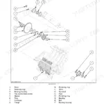
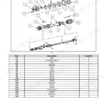
| Overhaul and Technical Specifications | 104-143 | Clearance Data, And 6 Engine Overhaul, Engine Removal at the Bench, Repair Operations, Cylinder Unit (Checks and Measurements, Checking Head Supporting Surface on Cylinder Unit) |
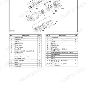
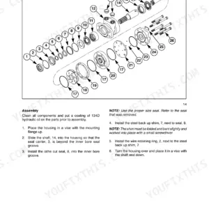
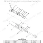
| Tools | 144-151 | Revolving Stand for Overhauling Units, Tool to Remove Output Shaft Front Gasket, Tool to Remove Output Shaft Rear Gasket, Tool to Remove Injectors |
| Appendix | 152-155 | Safety Prescriptions (Standard Safety Prescriptions, Prevention of Injury, During Maintenance, Respect of the Environment) |
Quick Reference Specifications
| Specification | Value | Page |
|---|---|---|
| All Models | ||
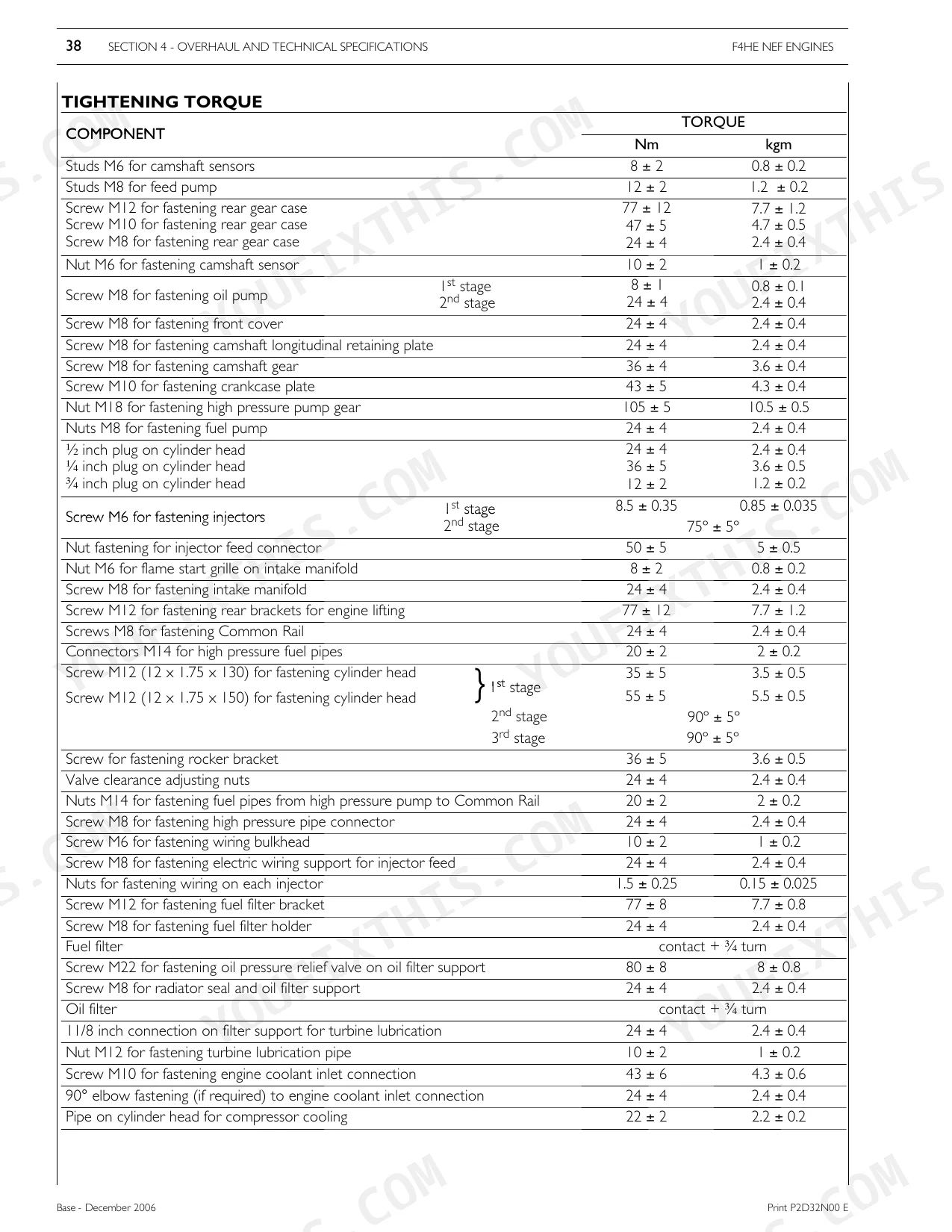
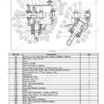
| Nut M18 for fastening high pressure pump gear | 105 ± 5 Nm | p. 141 |
| Screw M8 for fastening water pump | 24 ± 4 Nm | p. 141 |
| Screw for fastening fuel pressure sensor | 35 ± 5 Nm | p. 141 |
| Water temperature for engine overheating protection (performance reduction) | 110 °C | p. 31 |
| Thermostat Opening Temperature | 81 ± 2 °C | p. 45 |
| Injector Coil Impedance | 0.56 - 0.57 Ω | p. 81 |
| Crankshaft Sensor Impedance | ~900 Ω | p. 78 |
| Timing Sensor Impedance | ~900 Ω | p. 78 |
| F4HE9484A*J101 | ||
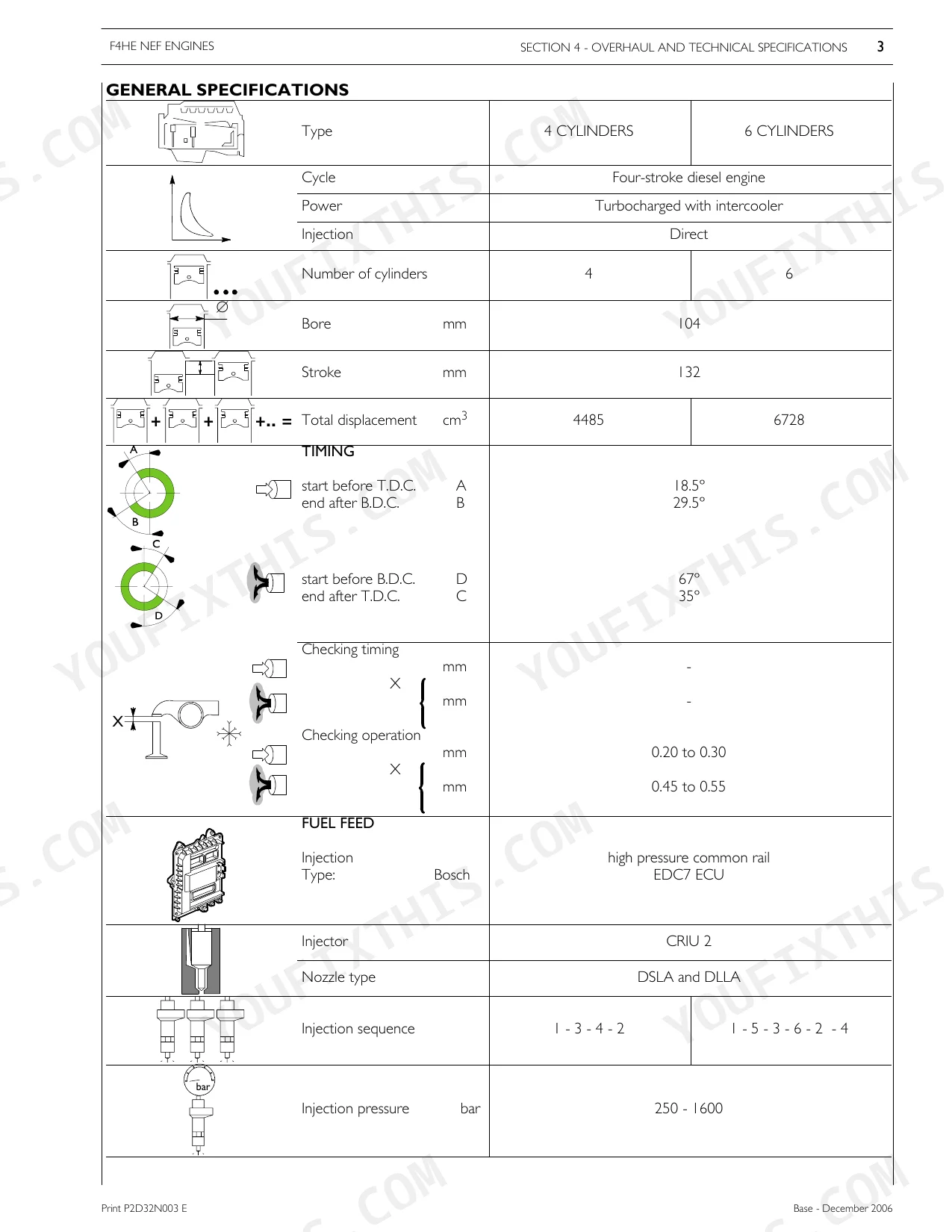
| Compression Ratio | 16.5 : 1 | p. 45 |
| Engine Oil Capacity (sump + filter) | 6.3 liters | p. 45 |
| 6-cylinder models | ||
| Compression Ratio | 17.5 : 1 | p. 46 |
| Engine Oil Capacity (sump + filter) | 15 + 1 liters | p. 46 |
Case IH Magnum 180-210 (NEF) Common Problems This Manual Covers
Fuel system pressure sensor fault code triggers repeatedly, engine performance fluctuates
Verify the sensor is seated and torqued to 35 ± 5 Nm per the torque spec on page 141. Check the wiring connector at the sensor for corrosion or spread pins using the pinout diagram. Clear the fault with the PT-01 tester and run the engine under load; if P0100 returns within 10 minutes, measure rail pressure against the spec in the Fuel section starting page 28. Inspect the high-pressure pump gear nut torque at 105 ± 5 Nm (page 141) before condemning the sensor itself.
Manual Section: Fault CodesEngine cranks but won't start in cold weather, glow plug light stays on longer than normal
Measure pre-post heating resistance at each glow plug: spec is ~0.5 Ω (page 82). An open circuit (infinite resistance) on any cylinder means that plug is dead. Check the crankshaft sensor impedance at ~900 Ω and the timing sensor at ~900 Ω (page 78); a cold sensor outside that range will prevent ECU from firing injection. Verify the pre-filter has no water ice, drain the water separator bowl before cranking again. Consult the no-start anomaly table for the full intervention sequence.
Manual Section: Troubleshooting AnomaliesValve train ticking noise at idle, increases with engine temperature and rpm
Adjust tappet clearance with the engine cold. Use the procedure to set clearance between rockers and valves for both intake and exhaust. Incorrect clearance after a head gasket job or valve grind is the most common cause of this complaint. Also inspect for oil blow-by at the head and engine pan; low oil pressure from a leak will accelerate rocker wear. For 6-cylinder models, oil sump capacity is 15 + 1 liters (page 46), verify the level is correct before running the adjustment.
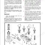
Manual Section: Inspection and Setting of Tappet ClearanceBlow-by filter clogged, excessive crankcase pressure, oil pushed past seals
Remove and inspect the blow-by filter cartridge per the procedure. A saturated or collapsed cartridge is normal at high hours but accelerates seal failure if ignored. Check for oil leakage or blow-by at the head, engine pan, and heat exchanger as described. On 6-cylinder models running 15 + 1 liters of oil (page 46), confirm the fill level is not overfull, which pressurizes the crankcase independently of filter condition. Replace the cartridge and recheck crankcase pressure after 2 hours of load operation.
Manual Section: Inspection/Replacement of Blow-by FilterFrequently Asked Questions
What are the torque values for the engine flywheel housing bolts on Magnum 210?
The torque values for fastening the engine flywheel housing bolts are 85 ± 10 Nm for M10 screws and 49 ± 5 Nm for M12 screws. These specifications are found in the tightening torque section of the manual. p. 142
What are the replacement specifications for the mechanical feeding pump?
The mechanical feeding pump, which is part of the high-pressure fuel pump assembly, cannot be replaced separately. It must not be disassembled from the high-pressure pump unit. p. 34
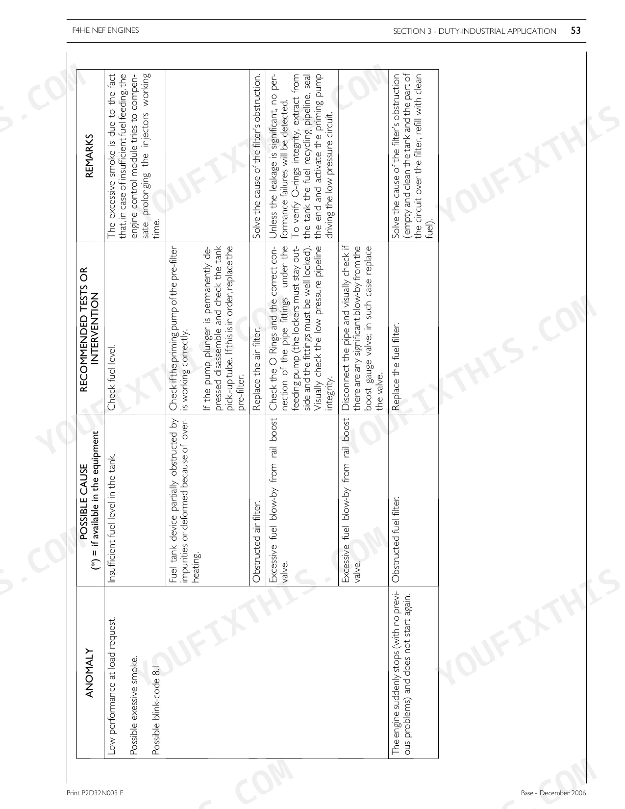
How do you fix case IH Magnum 180/190/210 engine loses power under load, black smoke from exhaust, rough running?
Check fault codes first using the PT-01 Portable Tester. Pull codes P0100 or P0200, which point to fuel metering or injection pump circuit faults. Inspect the pre-filter for water contamination and drain if present. Measure fuel pressure sensor torque at 35 ± 5 Nm (page 141). Verify injector coil impedance at 0.56–0.57 Ω per injector (page 81); replace any injector outside that range.
How do you fix engine overheats after 30 minutes of field work, coolant temperature warning active?
Inspect cooling system pipelines, fan belt tension, and all hose connections for leaks. The EDC7 control module begins reducing performance at 110 °C (page 31) to protect the engine. Verify the thermostat opens at 81 ± 2 °C; a stuck-closed thermostat is the most common culprit. If the water pump was recently serviced, confirm mounting screws are torqued to 24 ± 4 Nm (page 141). Clean the radiator core of crop debris before assuming pump failure.
How will I receive this Service Manual?
A 155-page Service Manual in searchable PDF format, available the moment you complete checkout. View on computer, tablet, or phone, with no shipping wait.
Is this Case IH Magnum 180 & variants Service Manual printable?
The PDF is DRM-free. Print whatever sections you need to take out to the shop. Standard letter or A4 paper works.
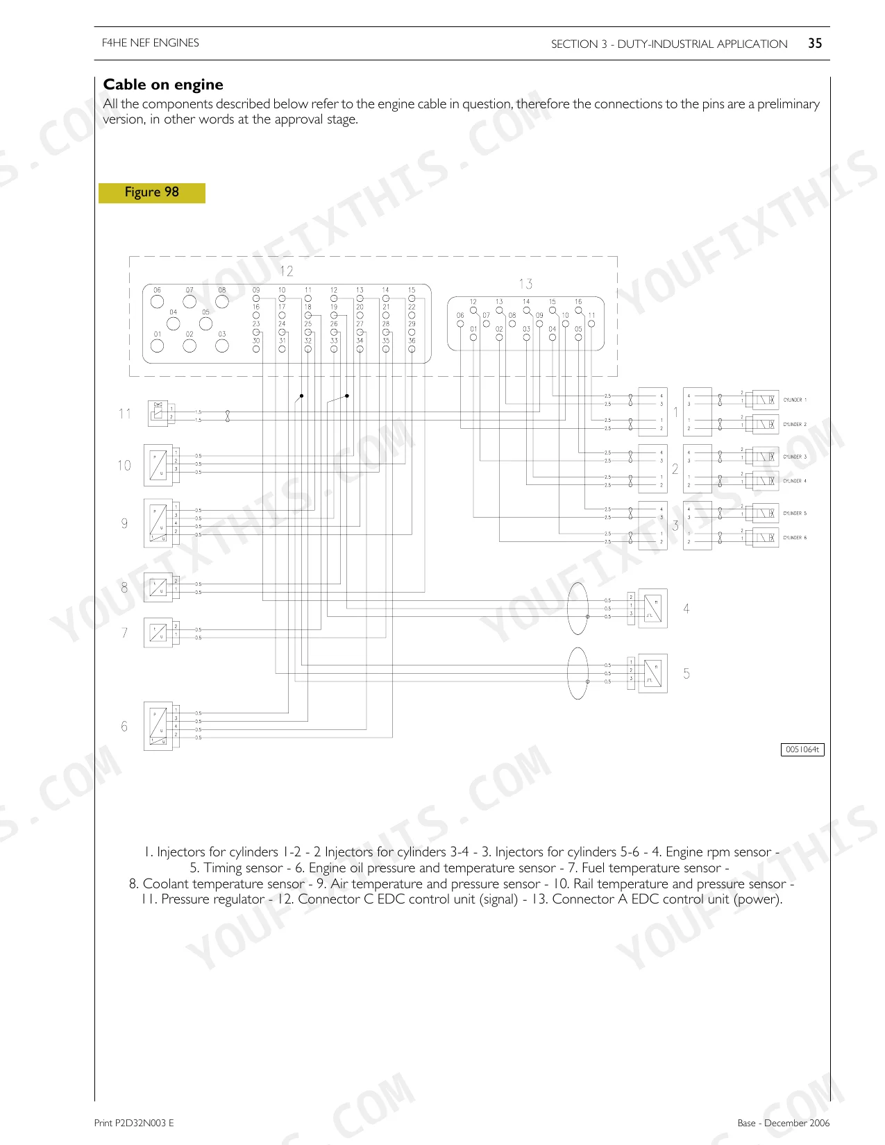
Are there wiring harness diagrams in this Case IH Magnum 180 & variants manual?
Yes, this Case IH Magnum 180 & variants Service Manual includes complete electrical wiring diagrams, wire routing, and connector pinouts.


Reviews
There are no reviews yet.