

Part of the Case IH Repair Manuals.
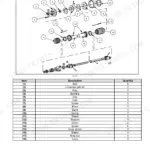
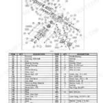
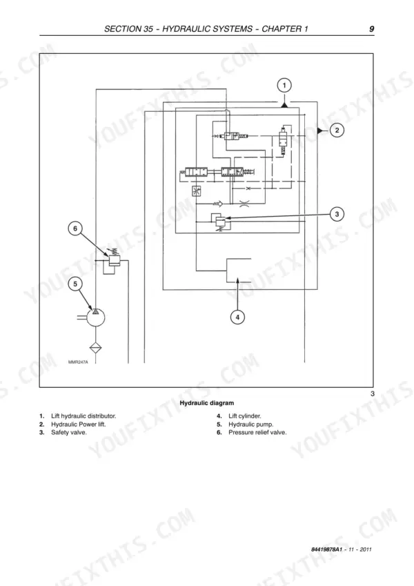
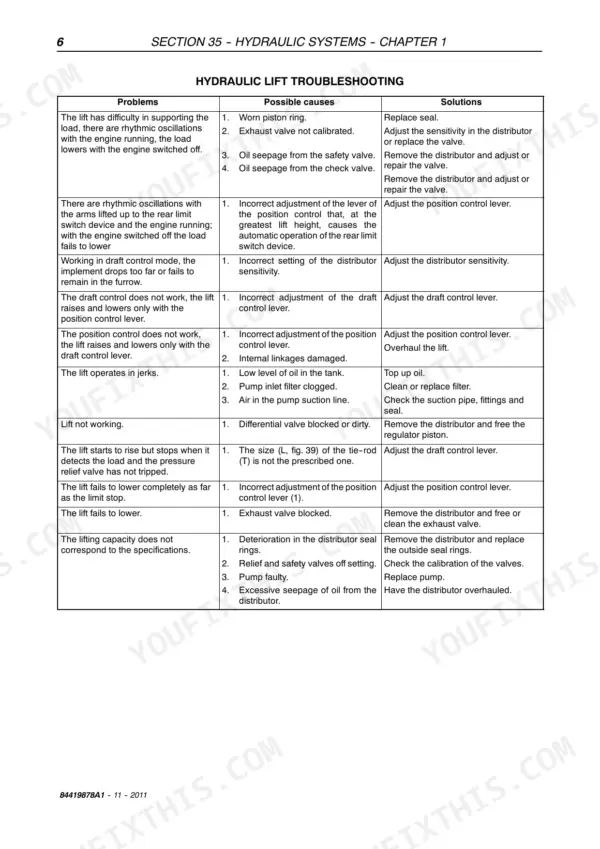
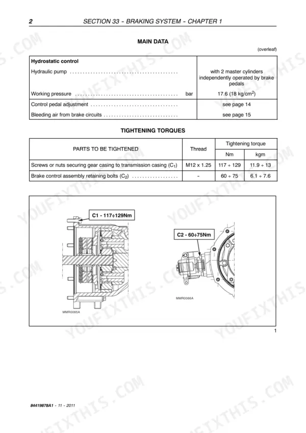
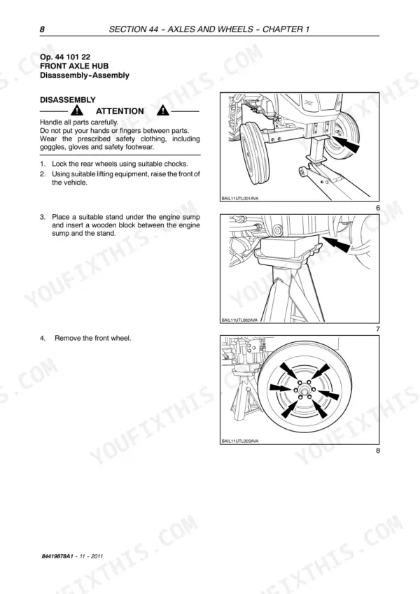
All 84 pages of this Case IH Farmall 55C, 65C, and 75C Service Manual (OEM #84419878A1) cover the 2011 tractor's seven core systems: front axle mechanical transmission, steering, brakes, hydraulics, cab HVAC, axles and wheels, and platform. You get full hydraulic schematics showing fluid routing through the three-point lift distributor and draft sensing unit, a troubleshooting section for every system from brakes to steering, and exploded-view diagrams for front epicyclic final drive overhaul, stub axle rebuild, and lift arm control shaft disassembly. Torque tables run through every assembly covered. Set your pressure regulating valve to 190–195 bar, check brake disk thickness at 4.7–4.8 mm, and torque the M12x1.25 gearbox-to-lift bolts to 117–129 Nm before closing up. Dealer wants a week; you need the number now. Bookmarked by system, searchable by keyword; pull it up on your tablet and start wrenching.
Complete the set for your FARMALL 55C, FARMALL 65C, FARMALL 75C
- Operator Manual: Case IH Farmall 75 Operator Manual
- Operator Manual: Case IH Farmall 75C, 85C, 95C, 105C, 115C Operator Manual
- Operator Manual: Case IH Farmall 45C, 55C Operator Manual
What's Inside This Case IH FARMALL 55C, FARMALL 65C, FARMALL 75C Manual
| System | Pages | Key Topics |
|---|---|---|
| General Guidelines | 3 | Safety Regulations, Tractor Refuelling |
| Front Axle Mechanical Transmission | 4 | Front Mechanical Transmission, Specifications, Tightening Torques, Tools, Sections, Removal-Installation Front Axle, Front Axle Disassembly - Assembly |
| Steering | 5 | Specifications, Tightening Torques, Tools, Sections, Description and Operation, View of Hydrostatic Steering Distributor Components, Troubleshooting |
| Cab HVAC System | 6-8 | Safety Regulations, Main Data, Tools, Operating Principles, Conditioning System Components, Cab Controls, Testing Operation and Cooling, Air Conditioning System Maintenance |
| Brakes | 9-14 | Main Data, Torque Settings, Sections, Special Tools, Description and Operation, Troubleshooting, Right or Left-Hand Brake. Removal - Installation |
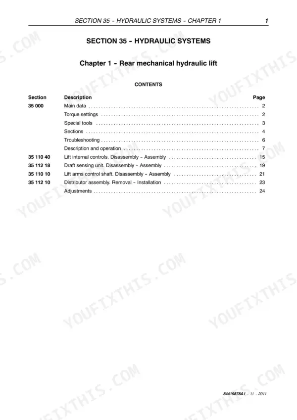
| Hydraulic Systems | 15-46 | Main Data, Torque Settings, Special Tools, Sections, Troubleshooting, Description and Operation, Lift Internal Controls. Disassembly - Assembly |
| Axles and Wheels | 47-68 | Main Data, Sections, Torque Settings, Special Tools, Troubleshooting, Front Axle Hub. Disassembly-Assembly, Front Axle. Removal - Installation, Stub Axle. Overhaul |
| Platform, Cab, Bodywork | 69-84 | Platform, Platform Assembly Removal-Installation, Removal, Installation |
Quick Reference Specifications
| Specification | Value | Page |
|---|---|---|
| Pressure regulating valve setting | 190 ÷ 195 bar | p. 16 |
| Cylinder safety valve setting | 220 ÷ 225 bar | p. 16 |
| Service Brake Disk Thickness | 4.7 ÷ 4.8 mm | p. 9 |
| Hydraulic Pump Working Pressure | 17.6 bar (18 kg/cm²) | p. 10 |
| Transmission Gearbox/Lift Retaining Bolts (M12X1.25) Torque | 117 ÷ 129 Nm | p. 16 |
| Lift Casing/Hydraulic Cylinder Retaining Bolts (M12X1.25) Torque | 98 ÷ 127 Nm | p. 16 |
| Engine Speed to Pump Speed Ratio | 1:1.08 | p. 43 |
| Front Axle Camber Angle | 2° (approx. 15 mm for 16" rims) | p. 47 |
| Front Axle Toe-in | 0 ÷ 5 mm | p. 47 |
| Axle Pivot Pin Retaining Bolt (C1) Torque | 49 Nm | p. 50 |
| Stub Head Locknut (C8) Torque | 102 ÷ 123.5 Nm | p. 51 |