

Part of the Case IH Repair Manuals.
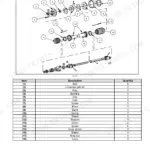
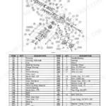
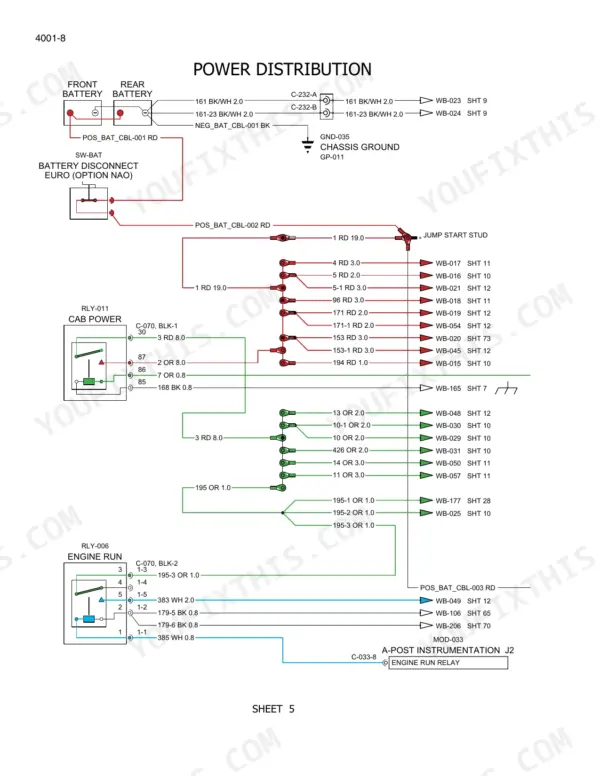
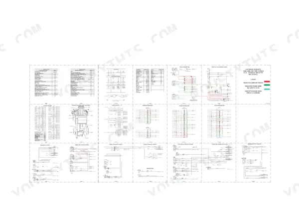
All 798 pages of this Case IH 5088, 6088, 7088 Service Manual (OEM #84242801) put your combine's electrical, hydrostatic, and chassis systems on the table in factory detail. Inside you get full wiring schematics with connector pinout data, hydraulic schematic posters covering both pre- and post-PIN Y8G000101 builds, and a dedicated troubleshooting section for starter and charging faults. You also get exploded views for the hydrostatic drive pump, final drive, and rotor bearing assembly, plus a complete torque chart for decimal, metric, and hydraulic fitting hardware. Set rotor front bearing housing clearance to 0.76-3.81 mm and torque the M12 bearing support bolts to 121-164 Nm before you button it back up. No more pulling panels just to trace a starting circuit by guesswork. This PDF carries clickable bookmarks for every section, so you jump straight from electrical to hydraulics without scrolling, on a laptop in the office or a tablet next to the header.
What's Inside This Case IH 5088, 6088, 7088 Manual
| System | Pages | Key Topics |
|---|---|---|
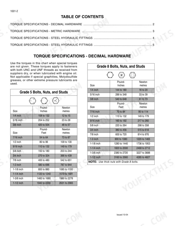
| General | 11-18 | Torque Specifications - Decimal Hardware, Torque Specifications - Metric Hardware, Torque Specifications - Steel Hydraulic Fittings, Loctite Chart |
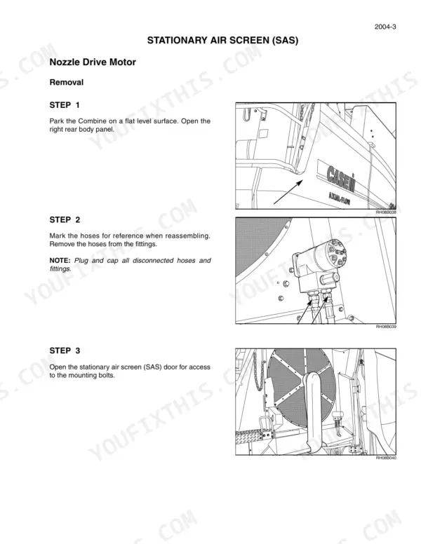
| Engine | 19-60 | Stationary Air Screen, Nozzle Drive Motor, Vacuum Fan and Rotating Arm, Engine Removal, Engine Installation |
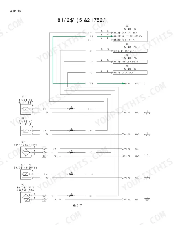
| Electrical | 61-238 | Electrical Schematics, Power Distribution, Starting and Charging System, Electrical Connectors Pinout Information, Combine Sensor Locations, Starter System Troubleshooting |
| Steering | 239-276 | Steering Cylinder, Steering Axle, Wheel Bearings, Toe in Adjustment, Power Guide Axle, Motor Removal |
| Power Transmission | 277-414 | Hydrostatic Drive Pump, Hydrostatic Motor, Transmission Removal and Installation, Final Drive Service, PTO Gear |
| Brakes | 415-434 | Brake Assemblies, Spring Return Assembly, Brake Housing, Brake Discs, Separator Plates, Friction Plates, Brake Hub, Service Piston |
| Hydraulics | 435-486 | Pfc Piston Pump, Auxiliary Pump, Stationary Air Screen System Pump, Hydraulic System Reservoir, Hydraulic System Pressure Screen, Hydraulic System Filtration, Piston Pump and Compensator Valve, Regulator/Unloader/Separator Valve |
| Chassis | 487-786 | Air Conditioning Troubleshooting, Safety Procedures, Special Tools, Evaporator/heater Assembly, Atc System, Smart Pressure Switch Cycling System, A/C Operation, Atc Wiring Schematic |
| Electrical / Hydraulic Schematics | 787-798 | Schematic Symbols, Component Abbreviations, Power Distribution, Starting and Charging System, Hydraulic System Schematic, Engine Control |
Quick Reference Specifications
| Specification | Value | Page |
|---|---|---|
| Clearance between rotor front bearing housing and rotor impeller blades | 0.76 to 3.81 mm (0.03 to 0.15 inch) | p. 662 |
| M12 Front rotor bearing support to bearing housing bolts torque | 121 to 164 Nm (90 to 121 lb. ft.) | p. 662 |
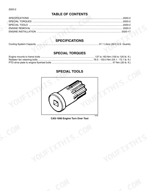
| Engine Cooling System Capacity | 37.1 Liters | p. 32 |
| Engine Mounts to Frame Bolts Torque | 137 to 163 Nm | p. 32 |
| PTO Drive Plate to Engine Flywheel Bolts Torque | 47 Nm | p. 32 |
| Steering Cylinder Retaining Bolts Torque | 122-163 Nm | p. 240 |
| Tie Rod Retaining Nut Torque | 332-366 Nm | p. 240 |
| Differential Pinion Shaft End Play | 0.05 to 0.15 mm | p. 307 |
| Shifter Rail Detent Springs Free Length | 44 mm | p. 307 |
| Final Drive Mounting Bolt Torque | 508 to 542 Nm | p. 366 |
| PTO Driven Gear Backlash | 0.102 to 0.203 MM | p. 404 |
| HVAC System Refrigerant Capacity | 6.5 lbs | p. 534 |