


Part of the Case IH Repair Manuals.
All 398 pages of this Case IH TerraFlex 3020 Auger Header Service Manual (OEM #47627573) are built around one mission: returning your header to factory condition, from the main gearbox and slip clutch through every hydraulic and electrical subsystem. Inside: full hydraulic schematics for the flex solenoid system and reel positioning circuits, plus wiring diagrams with complete harness and connector pinouts covering cab header controls, reel speed and position control, and the feeding control system. Exploded views walk you through the PTO drive shaft, feed auger, and cutting mechanism, with a troubleshooting section and torque tables rounding out the coverage. Set the moving knife clearance to 0.0–0.5 mm against the finger guards, then torque M16 wobble box arm bolts to 210–285 N·m (155–210 lb ft). Stop guessing at clearances. Bookmarked and searchable; pull it up on your tablet at the machine and get back to cutting.
What's Inside This Case IH 3020, TerraFlex 3020 Auger Header Manual
| System | Pages | Key Topics |
|---|---|---|
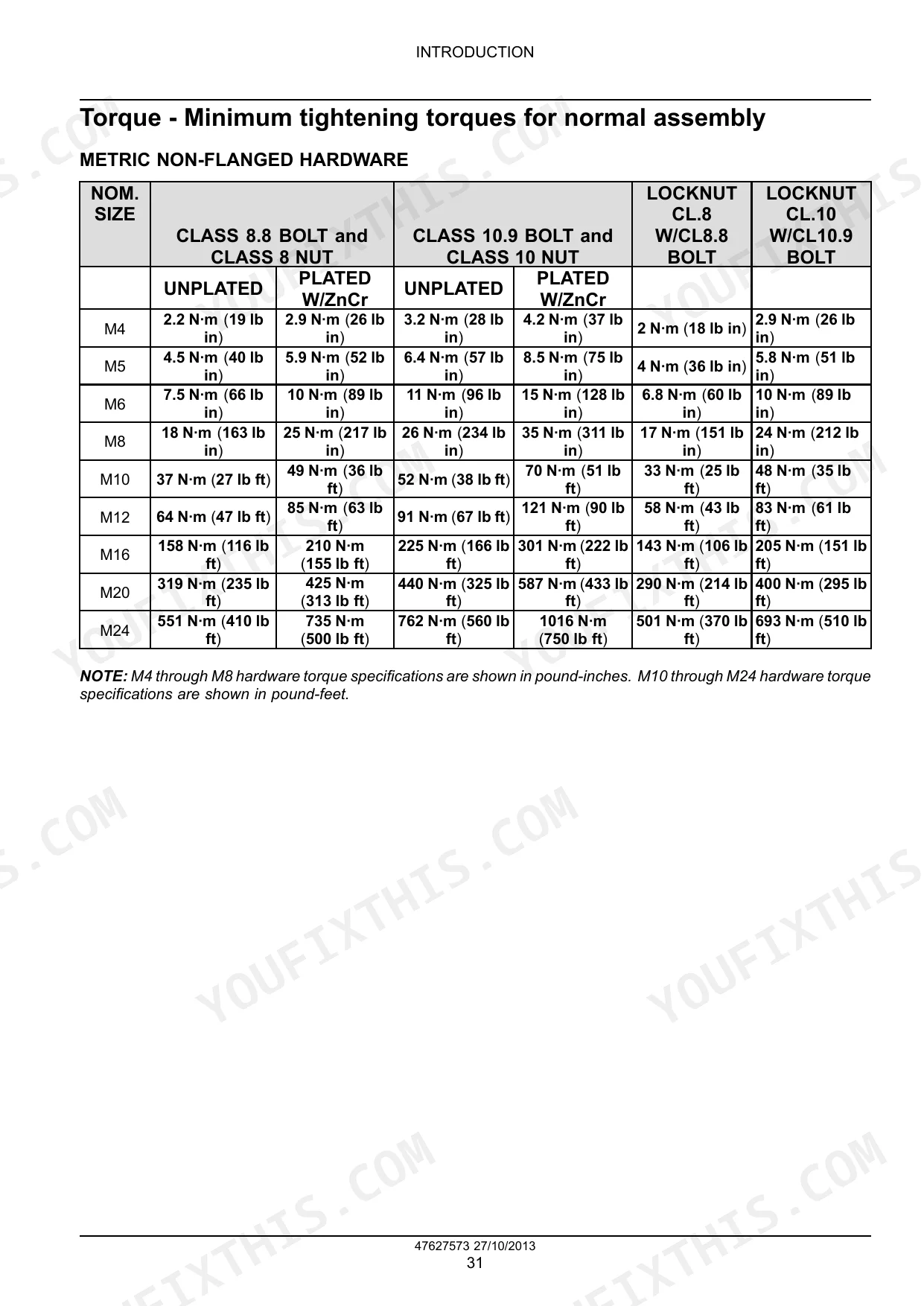
| Introduction | 6-51 | Basic Instructions - Shop and Assembly, Torque - Minimum Tightening Torques for Normal Assembly, Torque - Standard Torque Data for Hydraulics |
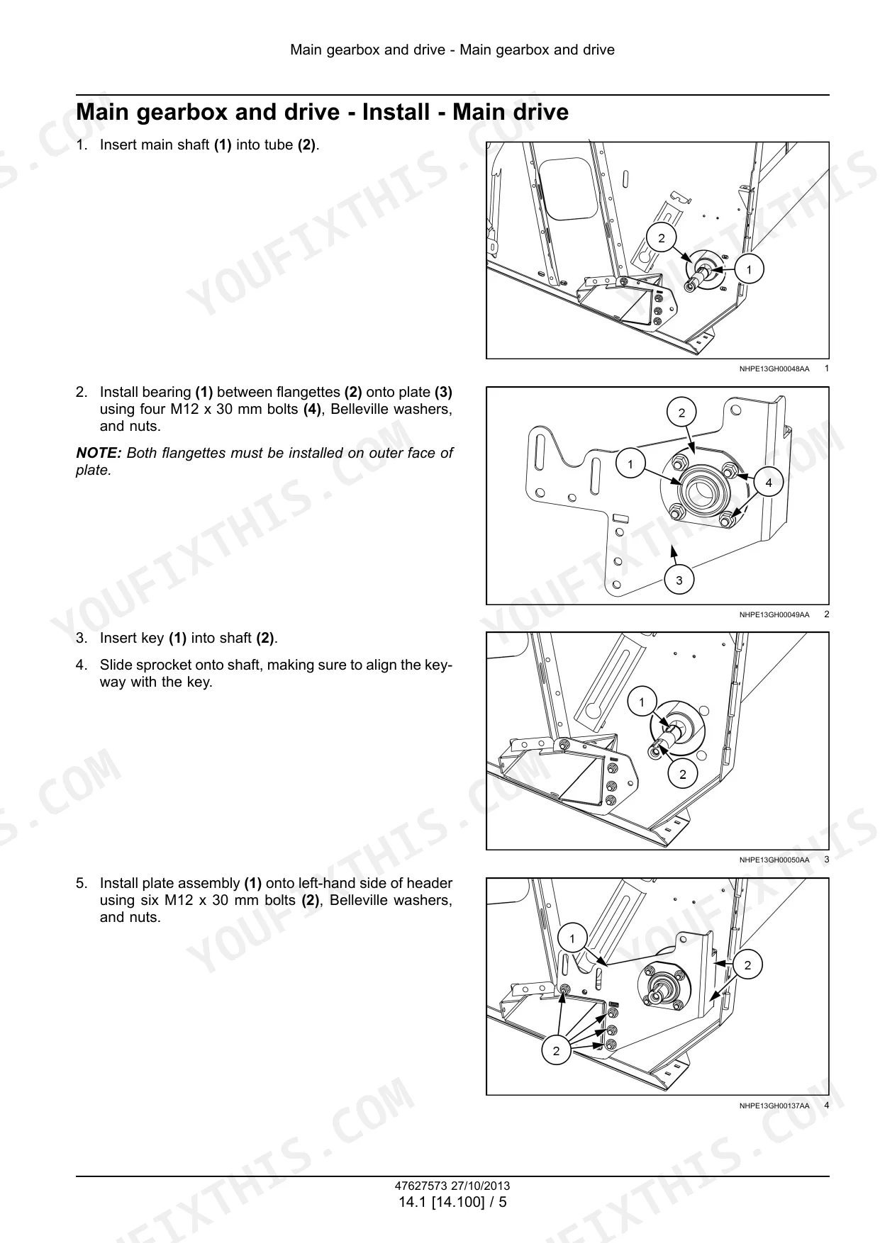
| Main Gearbox and Drive - 14 | 52-69 | Power Take-Off (PTO) Shaft - Exploded View - PTO Drive Shaft, Main Gearbox and Drive - Install - Main Drive, Main Gearbox and Drive - Tighten - Main Shaft Bearing |
| Clutch - 18 | 70-81 | Slip Clutch or Flywheel Damper |
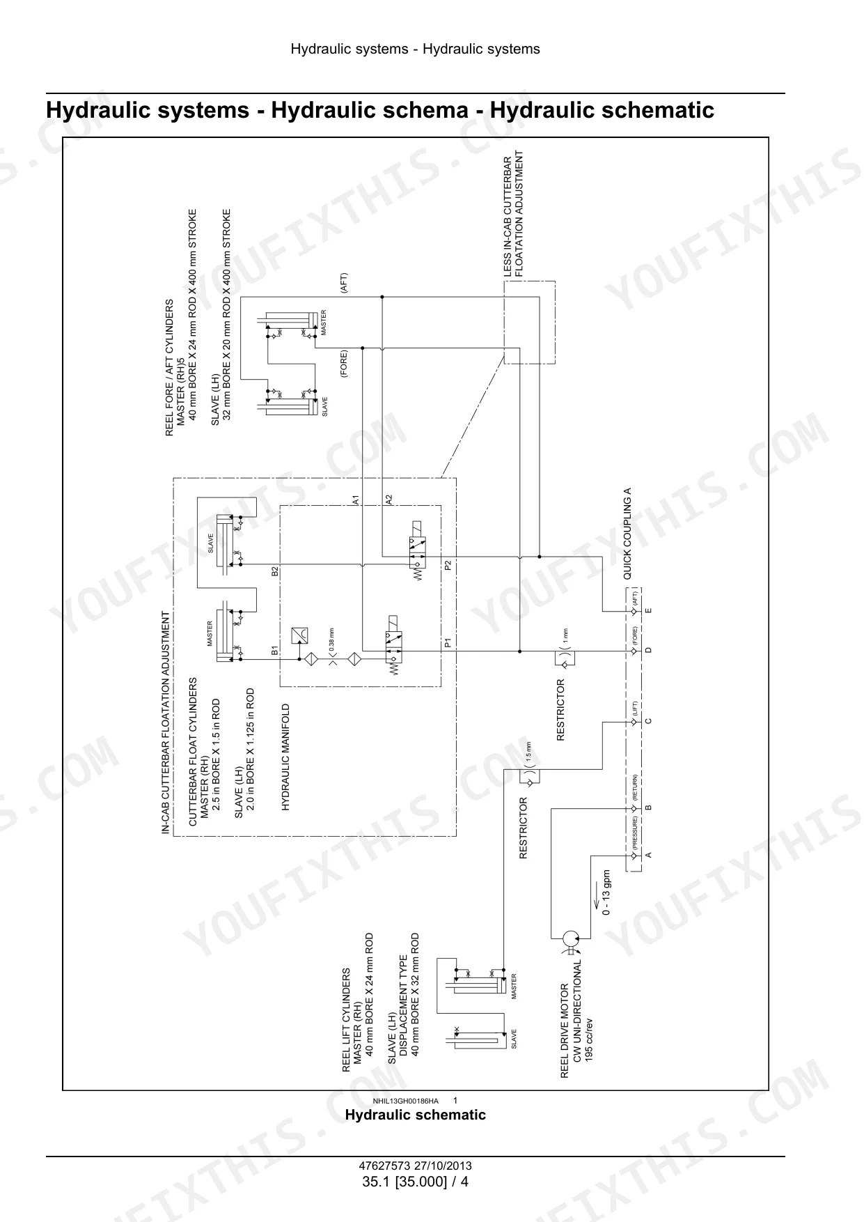
| Hydraulic Systems - 35 | 82-115 | Hydraulic Systems - General Specification - Flex Solenoids, Hydraulic Systems - Hydraulic Schema - Hydraulic Schematic |
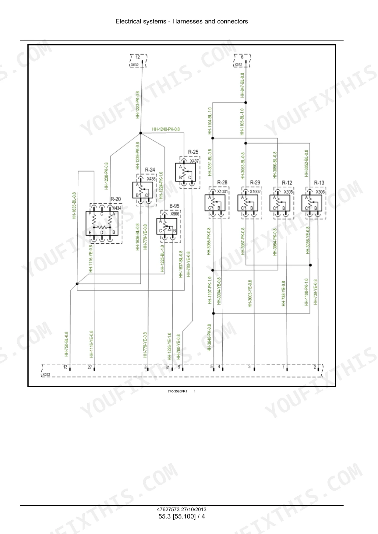
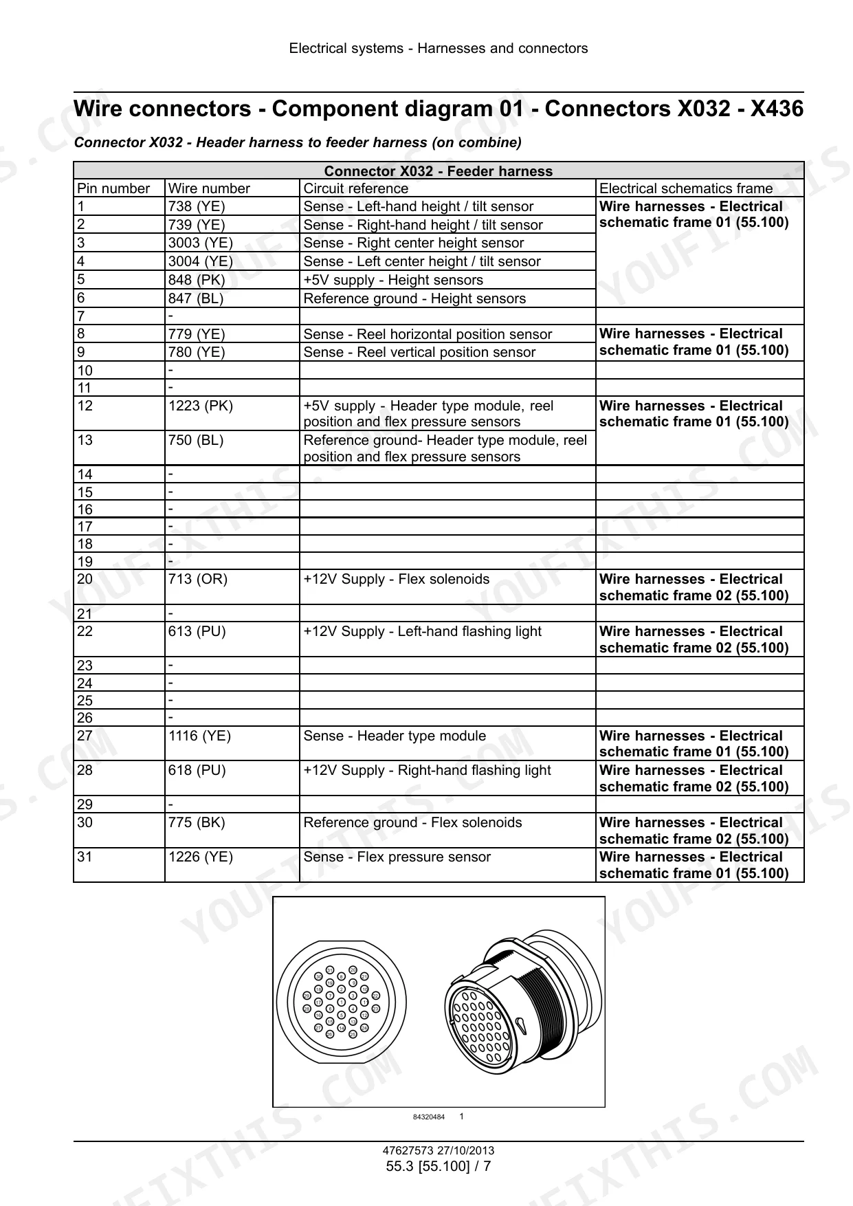
| Electrical Systems - 55 | 116-211 | Electrical System, Hydraulic System Control, Harnesses and Connectors, External Lighting, Feeding Control System, Cab Header Controls, Reel Speed and Position Control |
| Attachments/Headers - 58 | 212-375 | Attachment/Header Reel, Attachment/Header Reel Control System, Attachment/Header Cutting Mechanism, Attachment/Header Feed Auger, Attachment/Header Frame |
| Platform, Cab, Bodywork, and Decals - 90 | 376-398 | Machine Shields and Guards, Decals and Plates, Fenders and Guards |
Quick Reference Specifications
| Specification | Value | Page |
|---|---|---|
| Flex arm tension adjustment for ground pressure | 3 - 6 mm (0.12 - 0.24 in) off of the down stop | p. 291 |
| Clearance between hold-down clip and knife | 0.5 - 1 mm (0.020 - 0.039 in) | p. 286 |
| Clearance between moving knife and finger guards | 0.0 - 0.5 mm (0.0 - 0.02 in) | p. 287 |
| Rear floor to auger flight clearance | 13 - 17 mm (0.5 - 0.7 in) | p. 311 |
| Floor stripper to auger flight clearance | 5 - 9 mm (0.2 - 0.4 in) | p. 311 |
| Front floor to auger finger clearance | 18 - 22 mm (0.7 - 0.9 in) | p. 311 |
| Torque for auger cover bolts | 10 N·m (88.5 lb in) | p. 347 |
| Reel drive chain tension | just possible to move a link laterally across the sprocket by hand | p. 233 |
| Maximum allowable wear elongation for roller chain (general) | approximately 3 % | p. 42 |
| Clearance between hold-down clips and knife (with shims) | 0.1 - 1 mm (0.004 - 0.04 in) | p. 286 |
| Clearance between knife hold-down clips and knife (on press bar) | 0.5 - 1 mm (0.020 - 0.039 in) | p. 286 |
| M10, CLASS 8.8, UNPLATED bolt torque | 37 N·m (27 lb ft) | p. 35 |
Case IH 3020, TerraFlex 3020 Auger Header Common Problems This Manual Covers
Case IH 3020 sickle exhibits a wave and binds at the cutterbar during operation
Inspect the hold-down clips and shims on page 286. Adjust the clearance between the hold-down clips and the knife to 0.1 - 1 mm (0.004 - 0.04 in). Check the finger guards on page 287 and set the moving knife clearance to 0.0 - 0.5 mm (0.0 - 0.02 in).
Manual Section: Sickle cutterbar - Adjust - Hold-down clips p. 286Severe auger blockage and irregular crop feeding into the center of the header
Measure the clearance between the rear floor and the auger flight. Set this distance to 13 - 17 mm (0.5 - 0.7 in) as shown on page 311. Verify the front floor to auger finger clearance measures 18 - 22 mm (0.7 - 0.9 in) to ensure smooth crop flow.
Manual Section: Attachment/Header Feed Auger p. 311Left side drive chain slips on the sprocket or exhibits excessive play
Measure the roller chain for wear elongation on page 42. Replace the chain if elongation exceeds the 3 % maximum allowable limit. Tension the new reel drive chain on page 233 until it is just possible to move a link laterally across the sprocket by hand.
Manual Section: Main Gearbox and Drive - 14 p. 42Header pushes dirt and fails to float properly over uneven ground conditions
Set the flex arm tension on page 291 by turning the adjustment mechanism. Verify the flex arm rests exactly 3 - 6 mm (0.12 - 0.24 in) off of the down stop. Test the flotation response in the field to ensure the header glides over uneven terrain.
Manual Section: Attachment/Header Frame p. 291Frequently Asked Questions
How to reset CASE IH 3020 sensor calibration voltage?
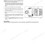
The manual describes configuring the header type module and adjusting potentiometers for height/tilt sensors, which involves setting voltage outputs. For combines with a 10 V sensing system, switch electrical connectors labeled "LH HT/TILT" and "RH HT/TILT" from the back sensor (1) to the front sensor (2). For 5 V systems, ensure connectors are plugged into the correct sensors and link rods are in the upper (3) and forward (4) mounting holes on both sides of the header. p. 192
Torque specs for CASE IH 3020 chain drive bolts
For the reel drive system, tighten the mounting bolts to 100 N·m (74 lb ft) after adjusting the chain tension. For the feed auger drive chain, install the M16 x 40 mm bolt (1), 16 mm lock washer, and 16 x 58 x 6 mm washer (2), then torque to 228 - 279 N·m (168.2 - 205.8 lb ft). p. 233
How to reset CASE IH 3020 guard and section inspection after wear
After wear, adjust the hold-down clips (1) with shims (2) to achieve a clearance of 0.1 - 1 mm (0.004 - 0.04 in) at (3). Adjust knife hold-down clips (1) using nut (2) on press bar (3) for a clearance of 0.5 - 1 mm (0.020 - 0.039 in) between the clip and knife (4). For auger headers before PIN YCH210001, fit the first two hold-down clips (1) on the left-hand side of the knife without a press bar, adjusting clearance to be between 0.5 - 1 mm (0.020 - 0.039 in) by bending the clips. p. 286
How to reset CASE IH 3020 flex arm pressure for ground conditions
To adjust the cutter bar weight (ground pressure), raise the cutterbar approximately 305 mm (12 in) off the ground. Adjust the torsion spring tension until the flex arm (1) is 3 - 6 mm (0.12 - 0.24 in) off of the down stop (2). Turning nut (1) counterclockwise lightens the cutterbar (reduces ground pressure), while turning it clockwise increases the weight. p. 291
Is this manual a digital download?
You get a 398-page searchable PDF that downloads instantly after checkout. Open it on your laptop, tablet, or phone, and bring it right to the shop floor.
Is this Case IH 3020, TerraFlex 3020 Auger Header Service Manual printable?
Yes. The PDF has no DRM restrictions, so print any page or section you need for your shop. Works with any standard printer.
Are there wiring harness diagrams in this Case IH 3020, TerraFlex 3020 Auger?
Yes, full electrical schematics are included with wire colors, connector locations, and circuit descriptions.


Reviews
There are no reviews yet.