


Need factory-level procedures for your Cnh Industrial F2CFE613A*B041, F2CFE613A*B, F2CFE613B*B, or any variant in the Cursor® 9 Tier 4B and Stage IV engine family? This 433-page service manual (OEM #48076851) is the complete factory reference for the F2CFE613 and F2CFE614 series. Inside: wiring diagrams and ECU pinouts covering the Engine Control System, SCR electrical circuits, and fuel injection, plus system diagrams tracing every fluid path from turbocharger lines to oil cooler routing. You also get step-by-step rebuild procedures spanning the crankshaft, cylinder heads, connecting rods, pistons, valve drive, and all pump drives, backed by torque tables and exploded views for every major assembly. Torque injector connections to 1.36–1.92 N·m (12–17 lb·in) and set calibration pressure to 290–302 bar (4,205–4,379 psi) before you button it up. Your machine is down. Grab the PDF, jump to any section by bookmark, and get the right spec before you've set down your wrench.
What's Inside This CNH Industrial Cursor 9 (F2CFE613 series) Manual
| System | Pages | Key Topics |
|---|---|---|
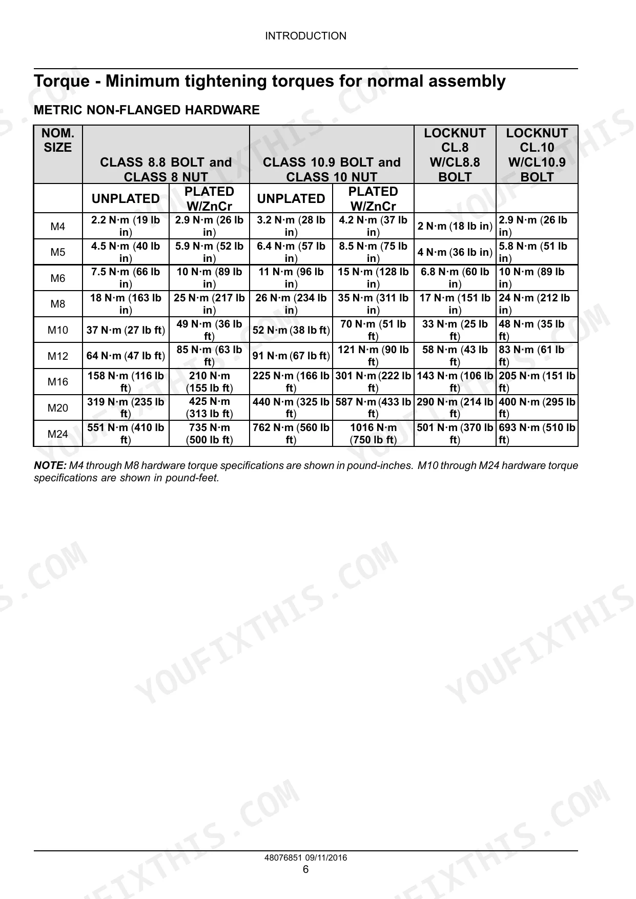
| Introduction | 7-24 | Foreword - Important Notice Regarding Equipment Servicing, Safety Rules, Safety Rules - Ecology and the Environment, Torque - Minimum Tightening Torques for Normal Assembly |
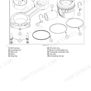
| Engine Mechanical - 10 | 25-161 | Engine and Crankcase, Pan and Covers, Valve Drive and Gears, Cylinder Heads, Connecting Rods and Pistons, Crankshaft and Flywheel |
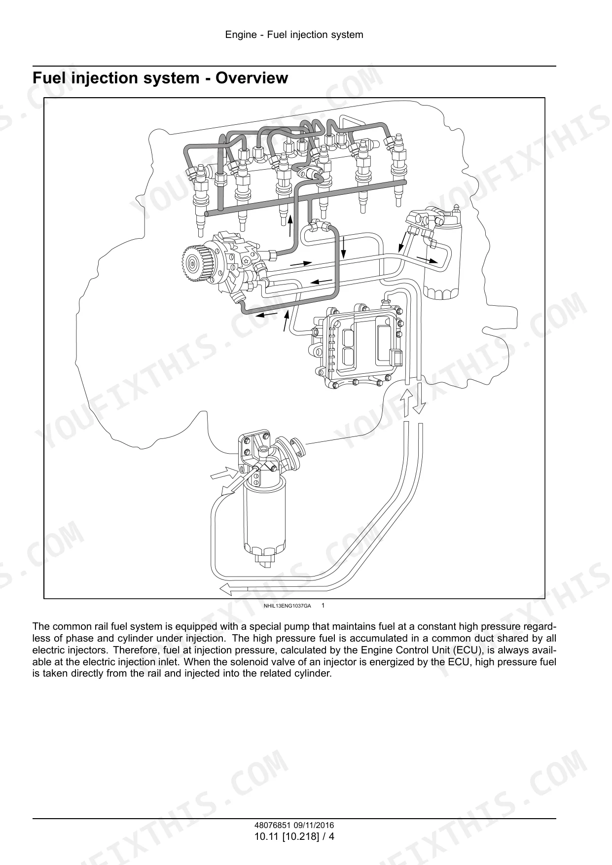
| Engine Fuel and Air Systems - 10 | 162-263 | Balancer and Damper, Pump Drives, Lift Pump and Lines, Fuel Filters, Fuel Injection System, Turbocharger and Lines, Intake and Exhaust Manifolds and Muffler, Selective Catalytic Reduction (SCR) Exhaust Treatment |
| Engine Cooling and Lubrication - 10 | 264-318 | Engine Cooling System, Fan and Drive, Engine Lubrication System, Oil Cooler and Lines |
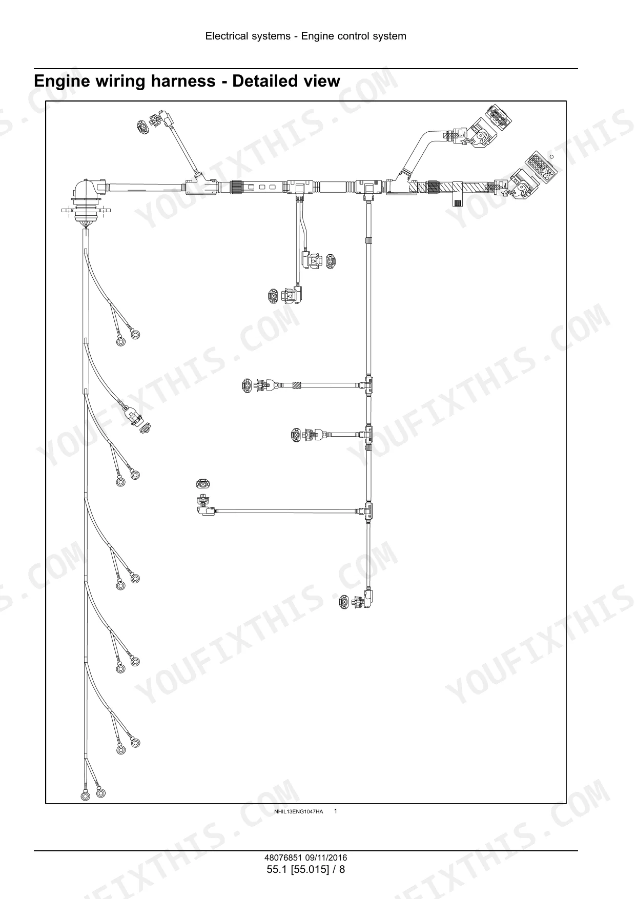
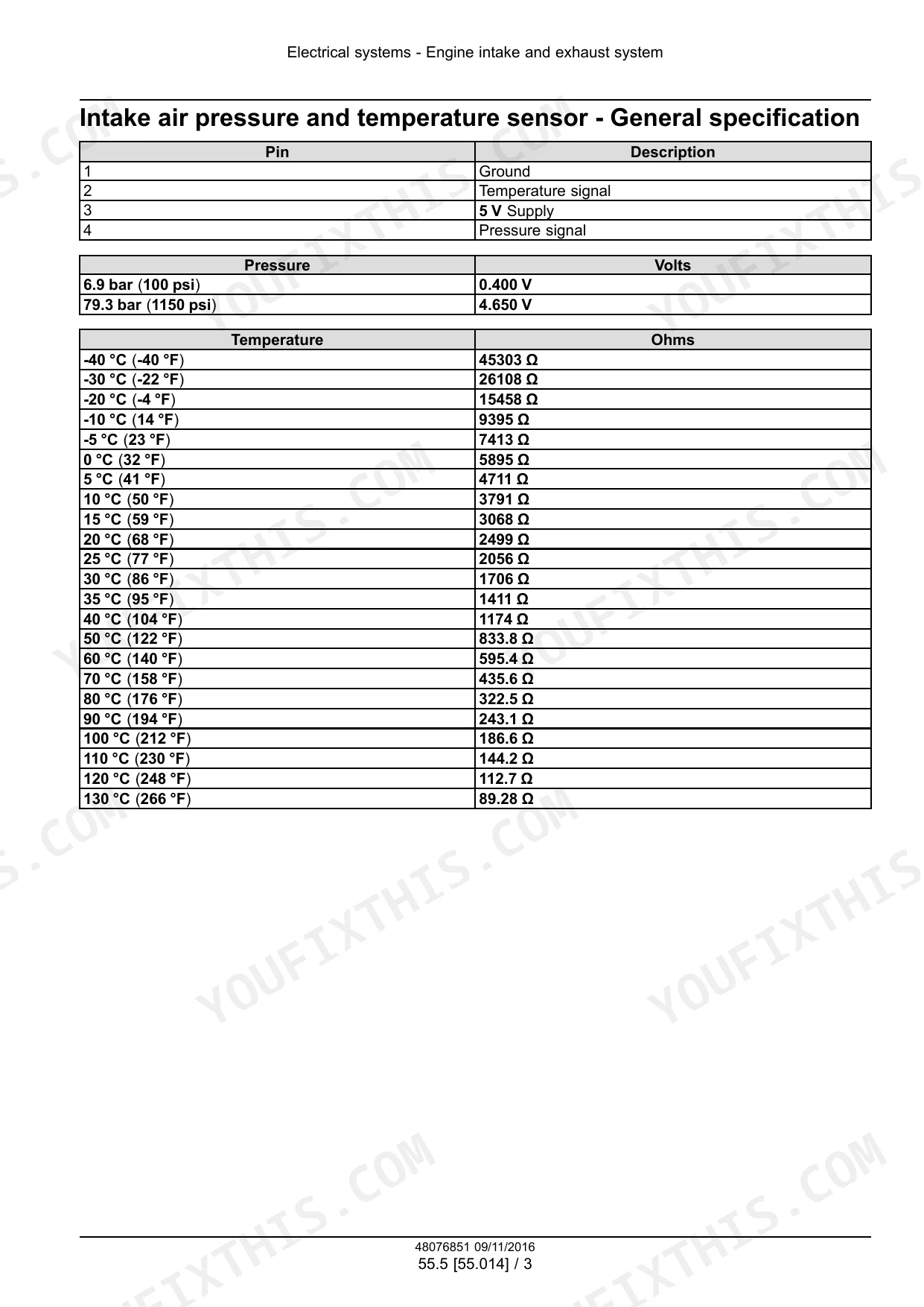
| Electrical Systems - 55 | 319-429 | Engine Control System, Engine Starting System, Alternator, Fuel Injection System, Engine Intake and Exhaust System, Selective Catalytic Reduction Electrical System |
Quick Reference Specifications
| Specification | Value | Page |
|---|---|---|
| Procedure for 'Replacement of the Rail Pressure Metering Unit – Reset ECU Data' | 1. Connect the Electronic Service Tool (EST) and turn the key switch ON without starting the engine. 2. Click the “Configuration” icon (1). 3. Select “Replacement of the Rail Pressure Metering Unit – Reset ECU Data” (1). 4. Click the “CONFIGURE SELECTED ITEM” button (2). 5. Click the “RESET” button (1). | p. 212 |
| Procedure for 'Replacement of the Rail Pressure Relief Valve (PRV) – Reset ECU Data' | 1. Connect the Electronic Service Tool (EST) and turn the key switch ON without starting the engine. 2. Click the “Configuration” icon (1). 3. Select “Replacement of the Rail Pressure Relief Valve (PRV) – Reset ECU Data” (1). 4. Click the “CONFIGURE SELECTED ITEM” button (2). 5. Click the “RESET” button (1). | p. 215 |
| Injector connections torque | 1.36 - 1.92 N·m (12 - 17 lb in) | p. 31 |
| Injector calibration | 290 - 302 bar (4205 - 4379 psi) | p. 32 |
| Piston measuring dimension | 15 mm (0.591 in) | p. 32 |
| Piston external diameter (supplied as spares) | 116.894 - 116.906 mm (4.602 - 4.603 in) | p. 32 |
| Turbocharger and lines torque (Pre-torque) | 35 N·m (26 lb ft) | p. 31 |
| Turbocharger and lines torque (Torque) | 46 N·m (34 lb ft) | p. 31 |
| Fuel filters torque | 19 N·m (14 lb ft) | p. 31 |
| Fuel filter installation tightening | 3/4 of a turn | p. 185 |
| Engine response to overheating | In the event of engine overheating, the control unit will "De-rate" the engine. This decreases the fuel delivery proportional to the temperature reached by the coolant. | p. 326 |
| Possible cause of engine oil leakage | Engine oil leakage can be caused by faulty seals or gaskets, excessive crankcase pressure, faulty lubrication system components, or the wrong engine oil. | p. 51 |
CNH Industrial Cursor 9 (F2CFE613 series) Common Problems This Manual Covers
Engine overheating under load, ECU de-rating power output, coolant temperature warning active
Inspect and clean the radiator core. Crop residue or chaff packed into fins is the most common cause on ag applications. Verify the thermostat begins opening between 83.5 - 86.5 °C (page 32) — a stuck-closed thermostat will trigger the same code. Note that per page 326, the ECU automatically de-rates fuel delivery proportional to coolant temperature. Restore full power only after root cause is corrected and coolant temps stabilize at normal operating range.
Manual Section: Engine Troubleshooting (General)Oil mixed with coolant in overflow tank, milky residue on dipstick
Check the troubleshooting index starting for coolant leak diagnostics. Remove pistons and inspect ring land clearances: combustion ring end gap should measure 0.3 - 0.4 mm; oil control ring end gap 0.35 - 0.65 mm in the cylinder liner (page 33). Measure piston-to-liner clearance — spec is 0.094 - 0.118 mm (page 32). Also inspect cylinder liner protrusion: must be 0.035 - 0.065 mm (page 32). Any liner sitting low allows coolant ingress past the seal.
Manual Section: Engine and CrankcaseHigh crankcase pressure, oil weeping from gaskets and seals at multiple points
Inspect for root cause per page 51: faulty seals or gaskets, excessive crankcase pressure, or wrong engine oil. Check the turbocharger oil return line for restriction — a blocked return raises crankcase pressure. Verify intake valve lash is set to 0.4 mm cold (page 32); tight valves contribute to blowby. Warm idle oil pressure should read at least 4 bar (page 32); low pressure combined with high crankcase pressure points to worn internal seals rather than external gasket failure.
Manual Section: Engine Troubleshooting (General) p. 51Engine cranks slowly or won't start in cold conditions, no fault codes present
Check the troubleshooting chart on for slow cranking and difficult start conditions. Test battery voltage under load before condemning the fuel system. Inspect both fuel filters — they are serviceable on-demand (page 372); a restricted secondary filter is a common cold-start culprit. Hand-tighten the filter 3/4 of a turn past gasket contact (page 185). Torque the filter head screws to 24.0 N·m (17.7 lb ft) (page 187) after any filter service.
Manual Section: Engine Troubleshooting (General)DEF/AdBlue dosing fault code, SCR system not regenerating, engine derate warning
Run the Urea Dosing System Test (UDST). Verify system pressure reaches 9.0 bar during normal operation (page 245) — low pressure points to a failed dosing pump or clogged DEF filter. Clean the DEF tank per the procedure if contamination is suspected. After any DEF component replacement, run the SCR fault repair verification test and reset the engine restart counter using the EST.
Manual Section: Selective Catalytic Reduction (SCR) exhaust treatment - Test - Urea Dosing System Test (UDST)Frequently Asked Questions
What are the torque specs for main bearing bolts on FPT Cursor 9 engine F2CFE613G*B001?
The main bearing bolts should be torqued in three stages. First, tighten to 140 N·m (103 lb ft). Then, apply an additional 60° of rotation in Stage 2, followed by another 60° rotation in Stage 3. p. 156
How to reset emission control system on FPT Cursor 9 engine F2CFE614H*B005?
To reset the emission control system, specifically the Engine Restart Counter, connect the Electronic Service Tool (EST) and turn the key switch ON without starting the engine. Navigate to the 'Configuration' icon, select 'Engine Restart Counter Reset / Unlock Inducement', click 'CONFIGURE SELECTED ITEM', and then click the 'RESET ENGINE RESTART COUNTER / UN LOCK INDUCEMENT' button. Similar procedures exist for Common Rail Relief Valve and SCR muffler/catalyst data resets. p. 252
What are the replacement specifications for Fuel injectors?
Fuel injectors must be replaced as a unit and should not be disassembled to avoid voiding the warranty. During installation, lubricate new injector seals with clean engine oil. Torque the M10x1.5 injector hold-down bolts to 46 N·m (34 lb ft), the rail mounting bolts to 26 N·m (19 lb ft), and the wire terminals for the injector coil to 1.5 N·m (13.3 lb in). p. 219
How do you fix CNH Industrial Cursor 9 Tier 4B engine losing power under load, black or white smoke from exhaust?
Connect the Electronic Service Tool (EST) and run a fuel system test per . Measure injector coil resistance at each injector: spec is 0.56 - 0.57 Ω (page 206). Replace any injector that tests outside this range as a complete unit — do not disassemble, as this voids warranty (page 219). Torque hold-down bolts to 46 N·m (34 lb ft) and fitting to 38 - 42 N·m (28 - 31 lb ft) on reinstall (page 220).
What do I get after purchasing this Cnh Industrial F2CFE613A*B041 & variants?
A 433-page Service Manual in searchable PDF format, available the moment you complete checkout. View on computer, tablet, or phone, with no shipping wait.
Is this Cnh Industrial F2CFE613A*B041 & variants Service Manual printable?
No restrictions at all. Print individual pages, full chapters, or the entire manual. The PDF is completely unlocked.
Does this Cnh Industrial F2CFE613A*B041 & variants manual have electrical?
Included. The Cnh Industrial F2CFE613A*B041 & variants Service Manual covers complete wiring harness diagrams, electrical circuits, and connector pinouts.
Reviews
There are no reviews yet.